


Reelmaster 2300–D/2600–D Hydraulic SystemPage 4 – 49
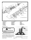
8. Inspect the wearplate (18) for cracks, peening, and
scoring. A polished pattern on the wear plate from rotor
rotation is normal. Replace as necessary.
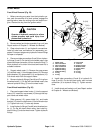
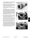
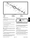
9. Inspect drive link (13) for cracks and worn or dam-
aged splines. No perceptible lash (play) should be noted
between mating spline parts of the rotor (19) or coupling
shaft (11). Replace as necessary (Fig. 39).
10. Inspect thrust bearing (12) for wear, peening, corro-
sion and a full complement of retained rollers. Replace
as necessary.
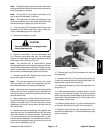
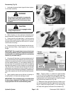
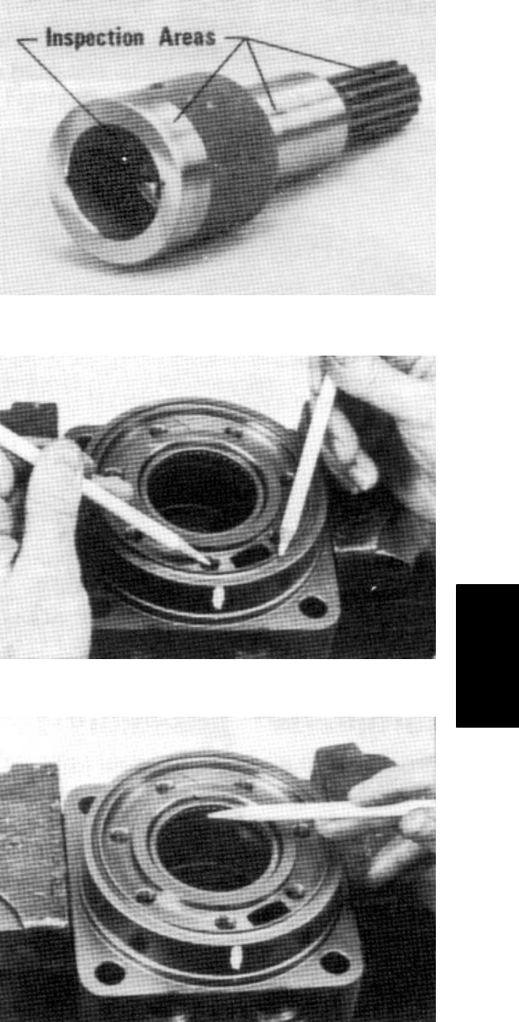
11. Inspect coupling shaft (11) internal and external
splines and keyway for damage and wear. Inspect bear-
ing and sealing surfaces of the coupling shaft for chip-
ping, nicks, grooves, severe wear, corrosion, and
discoloration. Replace coupling shaft if any of these
conditions exist. Minor shaft wear in seal area is permis-
sible. If wear exceeds 0.020 inch (0.51 mm) diametrical-
ly, replace coupling shaft. A slight ”polish” is permissible
on the shaft bearing areas (Fig. 40).
Note: Do not remove inner bearing (10), thrust wash-
ers (8), thrust bearing (9), inner seal (7), backup wash-
ers (6 and 4), and outer bearing (2) from the housing (3).
These parts should be inspected in place.
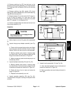
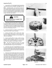
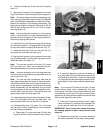
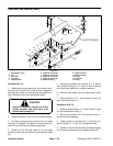
12. Inspect housing (3) for cracks. Inspect machined
surfaces for nicks, burrs, peening, and corrosion. Re-
move burrs that can be removed without changing di-
mensional characteristics. Inspect tapped holes for
thread damage. If the housing is defective in these
areas, discard the housing assembly (Fig. 41).
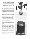
13. If the housing (3) has passed inspection to this
point, inspect outer bearing (2), inner bearing (10),
thrust washers (8), and thrust bearing (9). Bearing roll-
ers must be firmly retained in the bearing cages but must
rotate and orbit freely. All rollers and thrust washers
must be free of peening and corrosion. If any bearing or
thrust washer does not pass inspection, replace the
housing (3) as a complete assembly (Fig. 42).
Figure 40
Figure 41
Figure 42
Hydraulic
System