


Reelmaster 2300–D/2600–D
Page 5 – 17
Electrical System
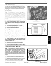
Component Testing
For accurate resistance and/or continuity checks, elec-
trically disconnect the component being tested from the
circuit (e.g. unplug the ignition switch connector before
doing a continuity check).
NOTE: Electrical troubleshooting of any 12 Volt power
connection can also be performed through voltage drop
tests without disconnecting the component.
NOTE: See the Perkins 100 Series Workshop Manual
for more component testing information.
CAUTION
When testing electrical components for
continuity with a multimeter (ohms set-
ting), make sure that power to the circuit
has been disconnected.
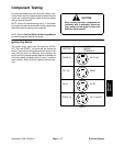
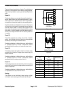
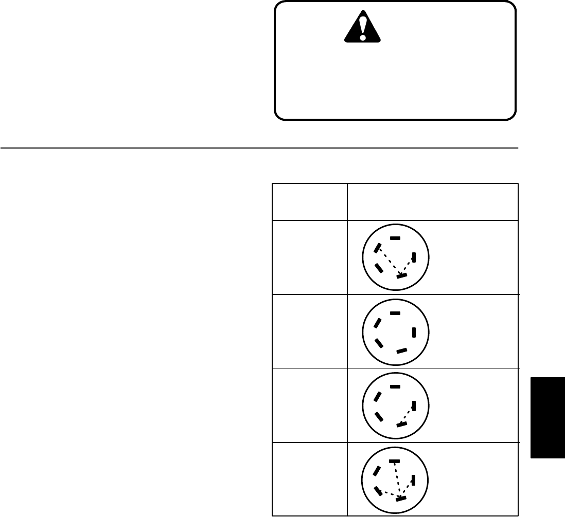
Ignition Key Switch
The ignition (key) switch has four positions (GLOW,
OFF, ON, and START). The terminals are marked as
shown. The circuitry of the ignition switch is shown in the
chart. With the use of a multimeter (ohms setting), the
switch functions may be tested to determine whether all
circuits are being completed while the key is moved to
each position. Verify continuity between switch termi-
nals.
Figure 3
POSITION
CONTINUITY
AMONG
TERMINALS
OFF (0) NONE
ON (1)
START (2)
30+19+AC
30+AC
GLOW (3)
50
19
17
30
AC
50
19
17
30
AC
50
19
17
30
AC
50
19
17
30
AC
30+17+50+AC
Electrical
System