


Reelmaster 2300–D/2600–D
Page 5 – 23
Electrical System
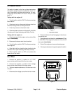
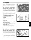
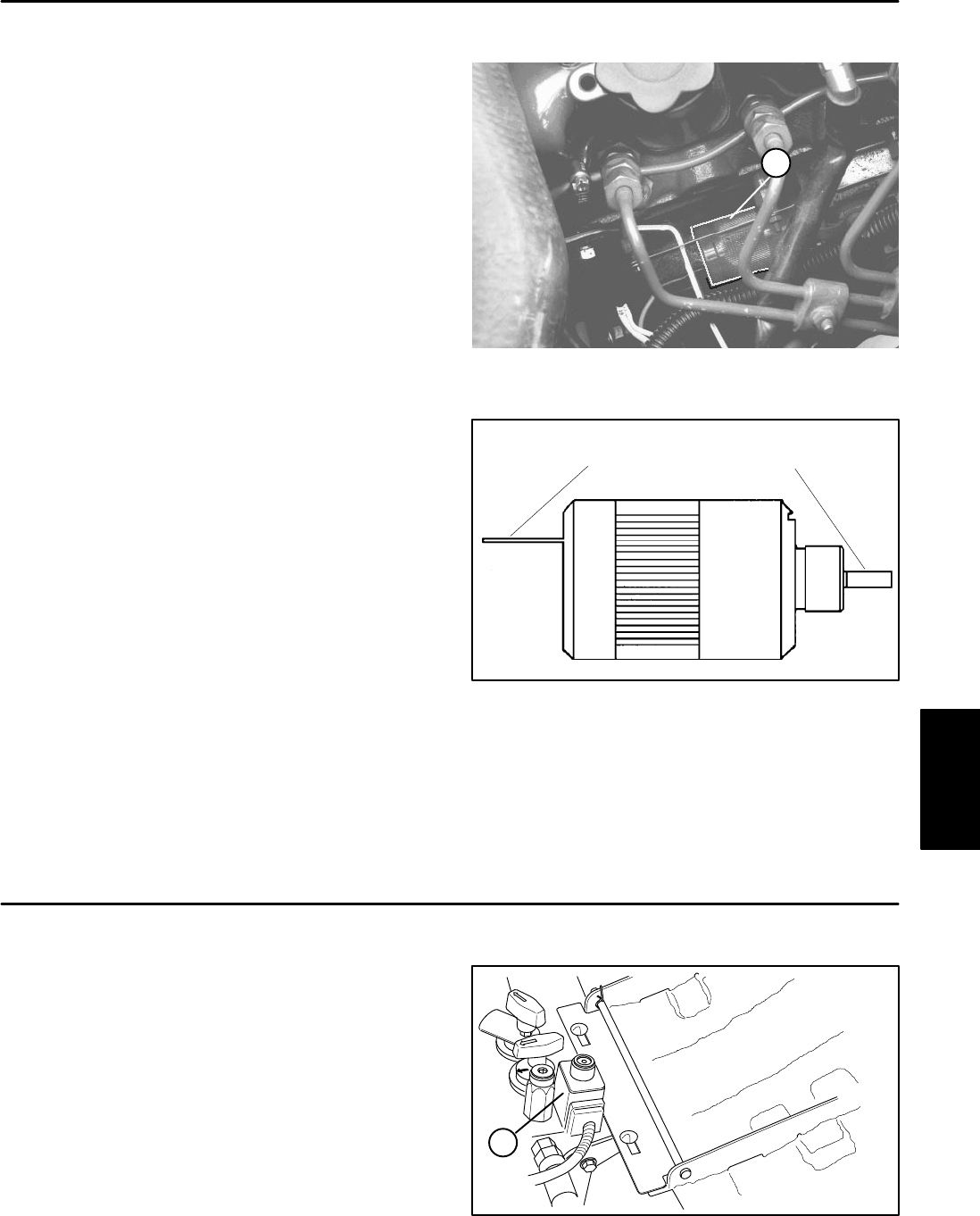
Fuel Valve Solenoid
The fuel valve solenoid must be energized for the en-
gine to run. It is mounted on the engine block next to the
injection pump and has a purple wire attached to it.
In Place Testing
Note: Prior to taking small resistance readings with a
digital multimeter, short the test leads together. The me-
ter will display a small resistance value (usually 0.5
ohms or less). This resistance is due to the internal re-
sistance of the meter and test leads. Subtract this value
from from the measured value of the component you are
testing.
1. Disconnect the wire from the solenoid.
2. Using a digital multimeter, ground one lead to the
engine block and connect the other to the solenoid ter-
minal.
3. The resistance should be about 11.5 ohms.
4. Connect the wire to the solenoid.
Live testing
1. Disconnect the wire from the solenoid.
Note: The solenoid may be removed from the engine
or tested in place.
2. Connect a positive (+) test lead from a 12 VDC
source to the solenoid terminal.
3. Touch a negative (–) test lead from the 12 VDC
source to the solenoid body. The plunger should retract
making an audible ”click”.
4. Disconnect the test leads from the solenoid.
5. Connect the wire to the solenoid if tested in place.
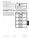
(! )u0l C-lC0 98l0n83.
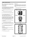
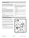
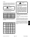
Figure 17
1
1
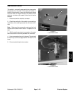
Figure 18
TERMINAL
PLUNGER
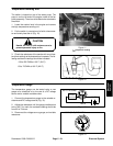
Cutting Unit Solenoid Valve Coil
Note: Prior to taking small resistance readings with a
digital multimeter, short the test leads together. The me-
ter will display a small resistance value (usually 0.5
ohms or less). This resistance is due to the internal re-
sistance of the meter and test leads. Subtract this value
from from the measured value of the component you are
testing.
1. Disconnect solenoid valve electrical connector.
2. Measure resistance between the two connector ter-
minals. The resistance should be about 7.2 ohms.
3. Connect solenoid valve electrical connector.
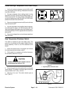
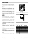
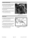
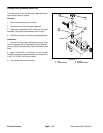
Figure 19
1
1. Solenoid Valve Coil
Electrical
System