Reelmaster 2300–D/2600–DPage 7 – 22Cutting Units
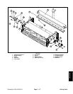
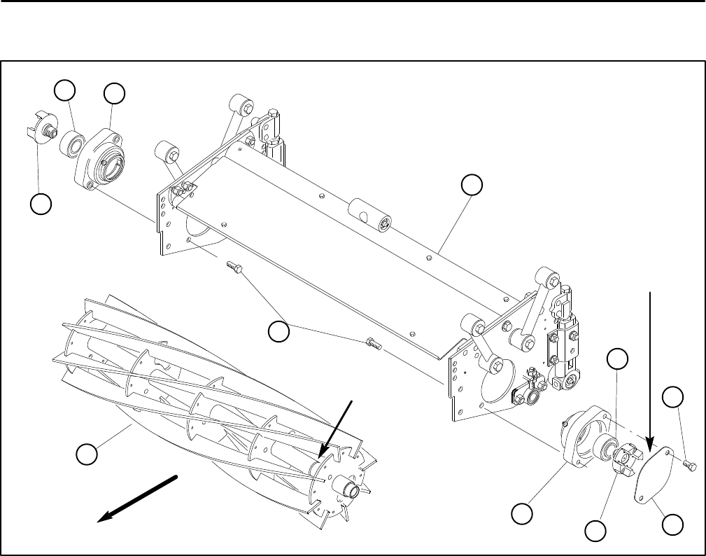
Reel Removal and Bearing Replacement
6
8
5
7
9
8
4
3
2
2
7
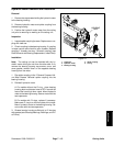
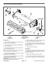
1. Cutting unit
2. Capscrew
3. Bearing cover
4. Male coupling (LH)
5. Male coupling (RH)
6. Capscrew
7. Bearing housing
8. Bearing
9. Reel
Figure 26
LEFT–HAND SIDE
FRONT
COVER GASKET
NOT SHOWN
GROOVE SHOWN
OUT OF POSITION
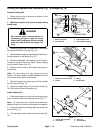
Remove Reel
1. Remove bedbar assembly from cutting unit (see
Bedbar Removal and Installation).
2. Remove front roller from cutting unit (see Roller Re-
moval and Installation).
3. Remove capscrews, bearing cover, and cover gas-
ket from the bearing housing.
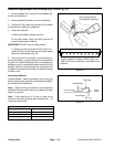
Note: A 3/8–inch drive ratchet with an extension will
fit into the square hole of the coupling.
4. Unscrew male coupling (LH) from the reel. This
coupling is left hand threaded.
5. Unscrew male coupling (RH) from the reel. This
coupling is right hand threaded.
IMPORTANT: Support reel to prevent it from dropping
when the bearing housings are removed.
6. Remove capscrews from both bearing housings.
Pull bearing housings and bearings from reel.
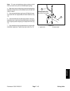
7. Rotate bearings within the bearing housings, and
remove bearings from both bearing housings through
the loading grooves.
8. Remove reel from cutting unit.
Inspect Reel
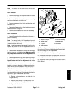
1. Replace reel if the diameter has decreased to the
service limit (see Reel Grinding Specification in Prepar-
ing Reel For Grinding)
2. Replace reel if blades are bent or cracked.
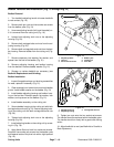
3. Check for a bent reel shaft by placing the reel shaft
ends in V–blocks. Replace reel if the reel shaft is bent.


