


Reelmaster 2300–D/2600–DHydraulic System Page 4 – 42
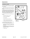
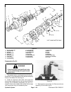
6. Inspect rotating parts kit (see Fig. 26).
A. Verify that piston O.D. finish shows no wear or
deep scratches. Piston shoes should fit snuggly
onto the ball end of the pistons. The shoe surface
that contacts the camplate should be smooth and
flat. Do not lap piston shoes.
B. Examine the mutual contact surfaces on the spi-
der and spider pivot; both contact areas should be
smooth and free of wear.
C. The piston block surface that makes contact with
the valve plate should be smooth and free of deep
scratches. Do not lap piston shoes.
D. The bore areas of the piston block should be free
of scoring and contamination. Pistons should move
freely in the bore areas.
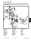
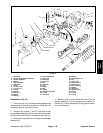
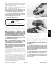
Reassembly (Fig. 24)
1. Make sure all parts are clean. Lubricate all critical
moving parts and O–rings with clean hydraulic oil.
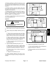
2. If necessary, press new bearing (14) into housing
assembly (15) to the dimension shown in Figure 29.
3. Insert camplate (20) into the housing assembly (15).
4. On the short trunnion side of the camplate (20),
install bearing (13) with numbered side to the inside of
the pump. Install inner race (12) with the chamfer to-
wards the inside of the pump. Install washer (11), O–ring
(10), O–ring cover (9), and trunnion cover (8). Secure
trunnion cover with two screws (7) torque them from 36
to 48 in–lb (42 to 55 kg–cm).
5. On the long trunnion side of the camplate (20),
install bearing (13) with numbered side to the inside of
the pump. Install washer (11) and press shaft seal (17)
into place. Secure seal cover( 16) with two screws (7)
and torque them from 36 to 48 in–lb (42 to 55 kg–cm).
6. Install retaining ring (32) towards the keyed end of
the shaft (31). Slide washer (33), thrust bearing (34), se-
cond washer (33), and second retaining ring (32) into
place over the splined end of the shaft.
7. Position washer (35) and shaft seal (36) onto the
shaft (31) from the keyed end.
8. Install shaft (31) into the housing assembly (15)
from the flanged end. Press shaft seal (36) into position
with a seal driver. Install retaining ring (37) into the
flanged end of the housing assembly (15).
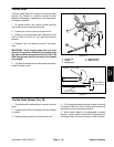
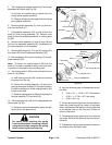
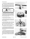
9. Reassemble rotating parts kit as follows (Fig. 26):
A. Use the following parts to reassemble the piston
block:
2 5/16 in. I.D. 15/16 in. O.D. flat washers
1 5/16 in. 2–7/8 in. N.C. cap screw
1 5/16 in. N.C. nut
B. Compress retainer and install into the spline of
the piston block.
C. Position the head end of pins towards the inside
of the block. Install the three pins into the special
grooves in the piston block.
D. Install a washer, spring, and second washer into
the piston block.
E. Place cap screw through one of the flat washers.
Insert cap screw through the center of the piston
block. Install second flat washer onto the capscrew
so the washer rests on the three pins. Screw nut
onto the cap screw.
F. Compress spring by tightening the nut onto the
cap screw. Install the retaining ring into the piston
block.
G. Unscrew the nut and remove washer and cap
screw from the piston block.
H. Install spider pivot onto the three pins and place
the spider on the spider pivot.
I. Insert piston assemblies through the spider and
into the piston block with the piston shoes resting on
the spider.
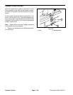
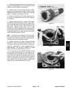
10. Set rotating kit assembly (29) on a working surface
with the piston shoes facing up. Insert shaft (31) through
the rotating kit assembly with the flanged end of the
housing assembly up. Position rotating kit assembly into
the housing assembly.
11. Make sure piston block and shaft (31) splines are
aligned. Make sure piston block is engaged fully so the
piston shoes are in contact with the camplate (20). Make
sure all parts are in their proper position be for pro-
ceeding to the next step.
12. Hold rotating kit assembly (29) in place, and clamp
housing assembly (15) with the flange end down into a
vise with protected jaws. Install gasket (24) and two
dowel pins (18) into the housing assembly (15).
13. If necessary, press new bearing (4) or roll pin into
backplate assembly (25) to the dimension shown in Fig-
ure 28. Bearing should be installed with numbered end
outward. Roll pin should be installed with split oriented
away from the bearing.