


Reelmaster 2300–D/2600–DHydraulic System Page 4 – 38
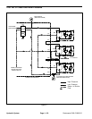
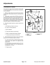
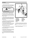
Removal (Fig. 23)
1. Before removing any parts, park the machine on a
level surface, engage parking brake, lower cutting units
and stop engine. Remove key from the ignition switch.
CAUTION
Operate all hydraulic controls to relieve system
pressure and avoid injury from pressurized hy-
draulic oil.
2. Clean pump assembly and hydraulic connections.
Label all hose connections for reassembly purposes.
Put caps or plugs on any hydraulic lines or fittings left
open or exposed. Install plug into the hydraulic reser-
voir.
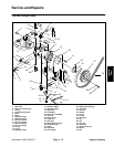
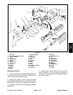
3. Remove both cap screws (1) from the pump assem-
bly. Carefully separate the reel motor drive pump (2) and
O–ring (3) from the traction/charge pump (4). Position
reel motor drive pump away from traction/charge pump.
4. Remove hoses (5 and 6) from hydraulic fittings (7
and 8). Remove hose connections (9, 10, 11, and 12)
from hydraulic fittings (15, 16, and 17). Allow hoses to
drain to a suitable container.
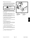
5. Remove cap screw (40) and lock nut (39) from the
pump control rod (41), spacer (42), and pump lever as-
sembly (20).
6. Loosen lock nut (21) at the pump mount (22) and nut
(43) at the belt adjustment yoke (25). Remove cotter pin
(23) and clevis pin (24) from the belt adjustment yoke.
7. Tilt pump mount (22) and remove pump drive belt
(26) from the pulley (27).
8. Remove cap screws (28) and lock washers (29)
from the pulley (27) and taper lock bushing (30). Run
cap screws into tapped holes in the pulley, then drive
pulley off the taper lock bushing.
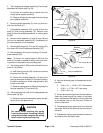
9. Support traction/charge pump (4). Remove both
cap screws (31), lock nuts (32), and washers (33) from
the traction/charge pump and pump mount (22). Sepa-
rate traction/charge pump from the pump mount.
Note: Steps 10 and 11 may be performed depending
on the extent of the pump repair.
10. Remove fittings (7, 8, 15, 16, and 17) and O–rings
(34 and 35) from the traction/charge pump (4).
11. Unscrew set screw (36) enough to loosen tapered
lock bushing (30). Slide tapered lock bushing off the
pump shaft. Remove key (37) from pump shaft.
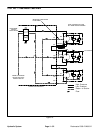
Installation (Fig. 23)
1. Mount the traction/charge pump (4) to the pump
mount (22). Place both cap screws (31) through the
pump mount and pump base. Install washers (33) and
lock nuts (32) onto cap screws. Tighten cap screws.
2. Place key (37) in the keyway on the pump shaft.
Slide taper lock bushing (30) into place on the pump
shaft. Tighten set screw (36).
3. Insert cap screws (28) through washers (29) and
pulley (27). Install pulley to taper lock bushing (30). Start
cap screws into bushing and leave cap screws loose.
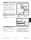
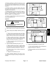
4. Loosen set screw (36) and adjust pulley (27) so the
gap between the pulley and pump mount is 0.20 inch.
Evenly torque cap screws from 90 to 120 in–lb. (104 to
138 kg–cm) three times each. Readjust as required.
5. Make sure mounting and O–ring sealing surfaces
on reel motor drive pump (2) and traction/charge pump
(4) are clean.
6. Inspect O–ring (3) and replace if damaged or worn.
Apply clean hydraulic oil to O–ring. Place O–ring on reel
motor drive pump (2).
7. Position reel motor drive pump (1) to traction/charge
pump (4). Secure reel motor drive pump to traction/
charge pump with cap screws (1).
8. Coat all O–rings with clean hydraulic oil. Install hy-
draulic fittings (7, 8, 15, and 16) and O–rings (34) into the
traction/charge pump (4). Torque these fittings from 23
to 27 ft–lb and as close to their original position.
9. Coat all O–rings with clean hydraulic oil. Install hy-
draulic fittings (17) and O–rings (35) into the traction/
charge pump (4). Tighten these fittings as close to their
original position as possible.
10. Connect hoses (5 and 6) to hydraulic fittings (7 and
8); tighten both hose clamps. Connect hose connec-
tions (9, 10, 11, and 12) to hydraulic fittings (15, 16, and
17). Tighten all hose connections.
11. Replace cap screw (40) through the pump control
rod (41), spacer (42) and pump lever assembly (20). Se-
cure lock nut (39) to the capscrew and tighten.
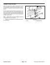
12. Install pump drive belt (26) onto pulley (27). Align
the holes of the mounting plate (22) with the holes of the
belt adjustment yoke (25) and slide clevis pin (24)
through holes. Secure clevis pin with the cotter pin (23).
13. Adjust pump drive belt (see Adjustments section)
Tighten lock nut (21) and torque from 60 to 70 ft–lb (8.3
to 9.7 kg–m).
14. Remove plug from the hydraulic reservoir.