


Reelmaster 2300–D/2600–D Hydraulic SystemPage 4 – 23
Procedure for Charge Pump Flow
Check:
1. Make sure hydraulic oil is at normal operating tem-
perature by operating the machine for approximately 10
minutes.
2. Make sure machine is parked on a level surface with
the cutting units lowered. Make sure engine is off and
the parking brake is engaged.
3. Make sure the hydraulic tank is full.
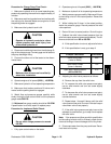
CAUTION
Operate all hydraulic controls to relieve
system pressure and avoid injury from
pressurized hydraulic oil.
4. Disconnect outside top hose from the discharge fit-
ting of the charge pump. Connect gage end of tester to
the pump discharge fitting.
5. Connect the other end of the tester to the discon-
nected hose.
CAUTION
Make sure that all hoses are free of the fly-
wheel after installation.
6. Operate engine at full speed (3200 100 RPM).
7. Make sure hydraulic oil is at operating temperature.
8. Make sure that traction pedal and lift valve are in
neutral and the parking brake is engaged.
9. Watch flow and pressure gauges carefully while
slowly closing the flow control valve until the pressure
gauge reads 500 PSI.
10. Minimum flow gauge reading should be 2.5 GPM.
If specification is not met, repair or replace pump.
Procedure for Implement Relief
Check:
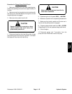
CAUTION
Do not allow charge pressure to exceed
650 PSI.
1. Fully open control valve on the tester.
2. Operate engine at full speed (3200 100 RPM).
3. Make sure hydraulic oil is at operating temperature.
4. Watch pressure gauge carefully. Make sure lift lever
to the cutting units is in the neutral position. Record the
pressure.
5. While holding the lift lever in the raised position,
watch the pressure gauge. Record pressure the relief
valve opens at.
6. Return lift lever to neutral position. Shut off engine.
7. Subtract the relief valve closed pressure from the
relief valve open pressure (see example below). The dif-
ference should be from 450 to 500 PSI.
A. If this specification is not met, adjust relief valve.
B. If this specification is met, go to step 9.
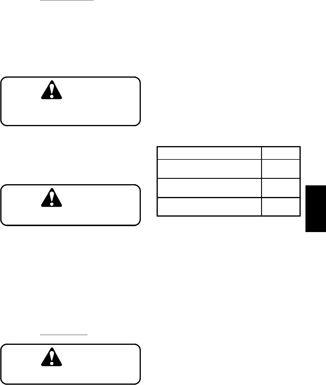
Example Calculation
PRESSURE
Relief Valve Open
(Lever to Raise)
620
Relief Valve Closed
(Lever in Neutral)
150
Open less Closed Pressure
(450 to 500 PSI)
470
8. Adjusting the relief valve pressure as follows:
A. Remove the cap from the relief valve.
B. To increase the relief valve pressure set point,
use an allen wrench and turn set screw slightly
clockwise.
C. To decrease the relief valve pressure set point,
use an allen wrench and turn set screw slightly
counterclockwise.
D. Repeat steps 1 through 8 above until the relief
valve pressure set point is correct. Reinstall cap on
valve when valve is set properly.
E. If the relief valve pressure set point can not be
adjusted to specification, go to step 9 and replace
the relief valve.
Note: If the pressure and flow are within specification
but the cutting units do not lift or lift slowly, check for me-
chanical binding or internal leakage of the lift cylinder.
9. Disconnect tester from the pump and hose. Recon-
nect hose to the pump.
Hydraulic
System