


Reelmaster 2300–D/2600–DHydraulic System Page 4 – 46
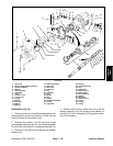
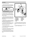
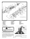
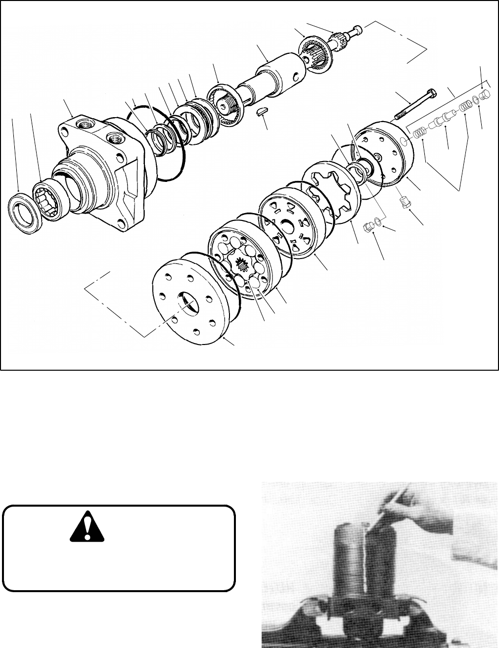
1. Dirt and water seal
2. Outer bearing
3. Housing
4. Backup washer
5. Seal ring
6. Backup washer
7. Inner seal
8. Thrust washer
9. Thrust bearing
10. Inner bearing
11. Coupling shaft
12. Thrust bearing
13. Drive link
14. Cap screw
15. Commutator seal
16. Commutator
17. Woodruff key
18. Wear plate
19. Rotor
20. Vane
21. Stator
22. Manifold
23. Commutator ring
24. End cover assembly
25. O–ring
Figure 32
1
2
3
4
5
6
7
8
9
10
16
17
18
19
20
21
22
23
11
12
13
14
15
8
24*
25*
25*
24
*LEFT HAND MOTOR ONLY
PLUG
24*
SHUTTLE
SPRING
(PLUG)
24* (PLUG)
VALVE
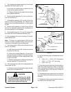
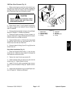
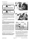
Disassembly (Fig. 32)
If the wheel motor is not held firmly in the
vise, it could dislodge during service and
cause injury.
WARNING
1. Place wheel motor in a soft jawed vice with the cou-
pling shaft (11) pointed down and the vise jaws clamping
firmly on the sides of the housing (3).
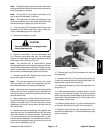
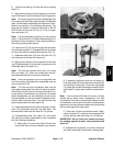
2. Scribe an alignment mark down and across the
wheel motor components from the end cover (24) to the
housing (3) for facilitating reassembly (Fig. 33). If in-
cluded in end cover, loosen both shuttle valve plugs
(left–hand motor only) for disassembly later.
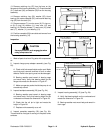
Figure 33
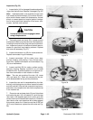
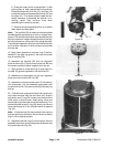
3. Remove seven cap screws (14). Remove end cover
assembly (24) and seal ring (5).