


Reelmaster 2300–D/2600–D
Page 5 – 31
Electrical System
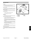
Traction (Electric) Clutch (Fig. 27 through 31)
The clutch circuit is normally energized when the engine
is starting or running. When energized, an electromag-
net pulls the armature into contact with the rotor to drive
the pulley and the traction motor through a fan belt.
Failure to engage the clutch is likely caused by too large
of a clutch air gap, a circuit fault in the clutch electromag-
net, or another electrical problem (see Wiring Schemat-
ics).
Note: The air gap is not adjustable. The clutch must
be serviced as a whole and individual parts can not be
replaced.
Removal
1. Make sure the engine is off and the fuel solenoid is
disconnected.
2. Lift the hood and disconnect the clutch electrical
connection. Make sure the connection is free of the
cable harness and the R–bracket holding it to the engine
block.
3. Remove the right and left front panels to access the
clutch and U–bracket support.
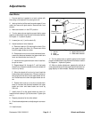
4. Remove the flanged nut securing the dampener to
the traction arm. Remove nut, lock washer and flat
washer securing the dampener to the U–bracket sup-
port. Remove the dampener (Fig 27).
5. Remove the two bolts, flat washers, and grommets
holding the tank to the U–bracket support. Remove the
nuts, carriage bolts, and U–bracket support from the
frame (Fig. 29).
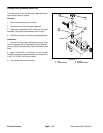
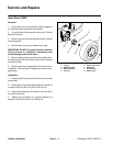
6. Loosen nut on adjusting yoke. Remove the cotter
and clevis pins from the adjusting yoke. Tilt pump mount
and remove the pump belt (Fig 28).
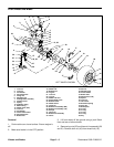
7. Remove long capscrew with the jam nut from en-
gine block. Retain the position of the jam nut on the
capscrew (Fig. 30).
8. Remove the spindle with the clutch attached by al-
ternately loosening all spindle capscrews and then pull-
ing on the clutch (Fig. 30). When the spindle is free of the
fly wheel, slide it up along the flywheel and rotate it out
to clear the traction pedal and foot rest.
9. Remove the capscrews, lock washers, and pulley
from the clutch (Fig. 30).
10. Remove the capscrew, lockwasher, and flat washer
from the spindle. Slide the clutch and key from the clutch
spindle (Fig. 30).
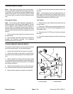
1. Flanged nut
2. Dampener
3. Traction arm
4. U–bracket support
Figure 27
4
1
2
3
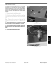
1. Nut
2. Cotter pin
3. Clevis pin
4. Adjusting yoke
5. Pump mount
Figure 28
2
2
1
4
5
Figure 29
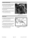
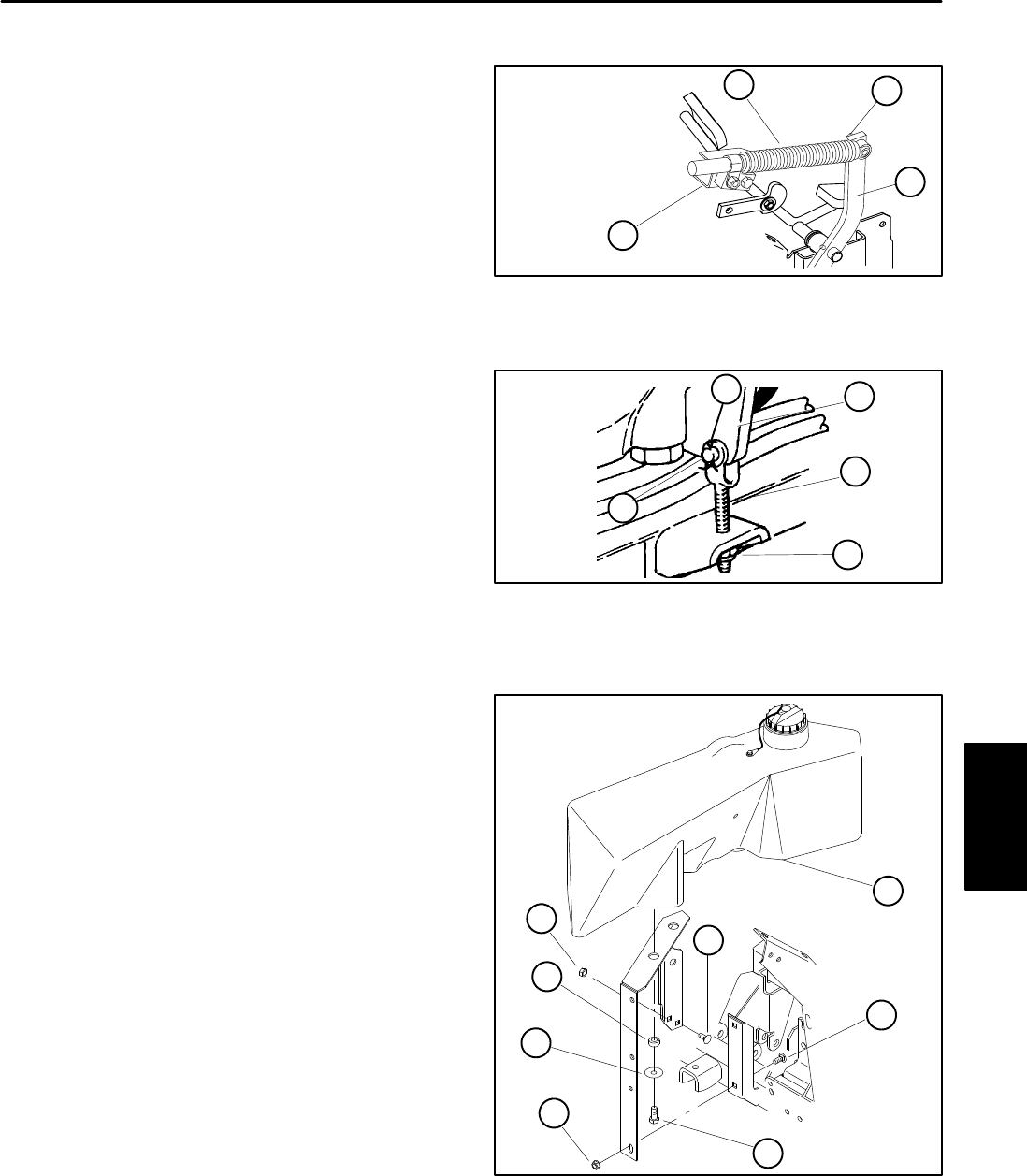
1. Capscrew
2. Flat washer
3. Grommet
4. Hydraulic tank
5. Nut
6. Carriage bolt
4
5
1
2
3
6
6
5
Electrical
System