


Reelmaster 2300–D/2600–DHydraulic System Page 4 – 48
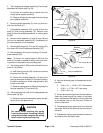
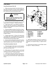
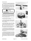
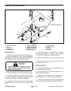
Inspection (Fig. 32)
1. Inspect bolts (14) for damaged threads and sealing
rings under the bolt head. Replace if damaged (Fig. 36).
Note: A polished pattern (not scratches) on the cover
from rotation of the commutator (16) is normal. Discolor-
ation would indicate excess fluid temperature, thermal
shock, or excess speed and require system investiga-
tion for cause and close inspection of end cover, com-
mutator, manifold, and rotor set.
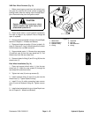
CAUTION
Use eye protection such as goggles when
using compressed air
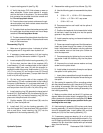
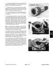
2. Thoroughly wash end cover (24) in proper solvent
and blow dry. Make sure the end cover valve apertures,
including the internal orifice plug, are free of contamina-
tion. Inspect end cover for cracks and the bolt head re-
cesses for good bolt head sealing surfaces. Replace
end cover as necessary (Fig. 37).
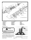
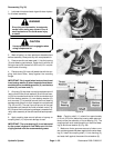
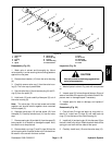
3. Inspect commutator ring (23) for cracks and burrs.
Replace commutator ring as necessary.
4. Inspect commutator (16) for cracks, burrs, wear,
scoring, chipping, and peening. If any of these condi-
tions exist, replace commutator and commutator ring
(23) as a matched set.
5. Inspect manifold (22) for cracks, surface scoring,
peening, chipping. Replace manifold if any of these
conditions exist. A polished pattern on the ground sur-
face from commutator or rotor rotation is normal.
Note: The rotor set consists of the rotor (19), vanes
(20), and stator (21). Rotor set components may be-
come disassembled during service procedures.
6. Inspect the rotor set in its assembled form for nicks,
scoring, and chipping on any surface. Inspect for broken
and worn splines. If the rotor set component requires re-
placement, the complete rotor set must be replaced as
it is a matched set.
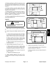
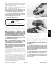
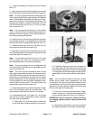
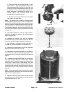
7. Place rotor set and wear plate (18) on a flat surface
and center the rotor (19) in the stator (21) such that two
rotor lobes (180 degrees apart) and a roller vane (20)
center line are on the same stator center line. Check the
rotor lobe to roller vane clearance with a feeler gage at
this common center line. If there is more than 0.005 inch
(0.13 mm) of clearance, replace the entire rotor set (Fig.
38).
Figure 36
Figure 37
Figure 38
Figure 39