


Reelmaster 2300–D/2600–DHydraulic System Page 4 – 68
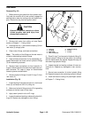
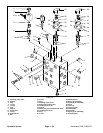
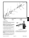
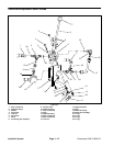
Removal (Fig. 59)
1. Before removing any parts from the hydraulic man-
ifold, park the machine on a level surface, engage the
parking brake, lower the cutting units and stop the en-
gine. Remove the key from the ignition switch.
CAUTION
Operate all hydraulic controls to relieve
system pressure and avoid injury from
pressurized hydraulic oil.
2. Raise and remove hood to get access to the front lift
cylinder. Label all connections for reassembly.
3. Disconnect hose connections (1), (2), (3), and (4)
from hydraulic fittings (5). Allow hoses to drain into a
suitable container.
4. Put caps or plugs on disconnected hoses and fit-
tings to prevent contamination.
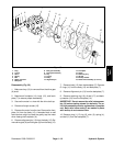
5. Remove hydraulic fittings (5) and O–rings (7) from
the lift cylinder (8).
6. Remove cotter pin (9) from the clevis pin (10). Pull
clevis pin from the lift cylinder (8).
7. Remove cap screw (11) from the lift hub (12).
Remove cotter pin (13) and clevis pin (14) from the
clevis (15) that is on the hydraulic fitting side of the
cylinder guide (15).
8. Support lift cylinder (8) and slide cylinder guide (16)
from the lift hub (12).
A. Reach up from the bottom and rotate lift cylinder
so the bottom port comes out of the slot in the frame.
B. Drop lift cylinder down and out from the frame.
Lift hub from the cylinder support bracket (17).
9. Remove flange bushings (18) from the cylinder
support bracket (17).
10. Remove lift hub (12) from the lift cylinder (8).
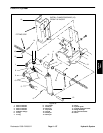
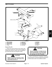
Installation (Fig. 59)
1. Thread lift hub (12) onto lift cylinder (8).
2. Position lift cylinder (8) inside the cylinder support
bracket (17) and valve mount bracket (19). Make sure
the inlet and outlet ports of the lift cylinder face the fitting
side of the cylinder support bracket.
3. Align lift cylinder (8) holes with holes at bottom of the
valve mount bracket (18). Slide clevis pin (14) through
holes and secure pin with cotter pin (9).
4. Align lift hub (12) holes with the slots on the cylinder
support bracket (17). Install flange bushings (18) into
the cylinder support bracket slots.
5. Make sure flange bushings (18) are aligned with the
lift hub (12) holes. Slide cylinder guide (16) through the
cylinder support bracket (17), flange bushings (18), and
lift hub (12).
6. Secure cylinder guide (16) by screwing cap screw
(11) fully into lift hub (12).
7. Secure clevis (15) to the cylinder guide (16) with cle-
vis pin (4) and cotter pin (13).
8. Slide clevis pin (10) through the valve mount brack-
et (19) and lift cylinder (8). Install and lock cotter pin (9)
into the clevis pin.
9. Install hydraulic fittings (5) and O–rings (7) into the
lift cylinder (8).
10. Remove caps or plugs from disconnected hoses.
Connect hose connections (1), (2), (3), and (4) to hy-
draulic fittings (5). Tighten hose connections