


Reelmaster 2300–D/2600–D Hydraulic SystemPage 4 – 63
Hydraulic Manifold
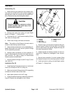
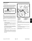
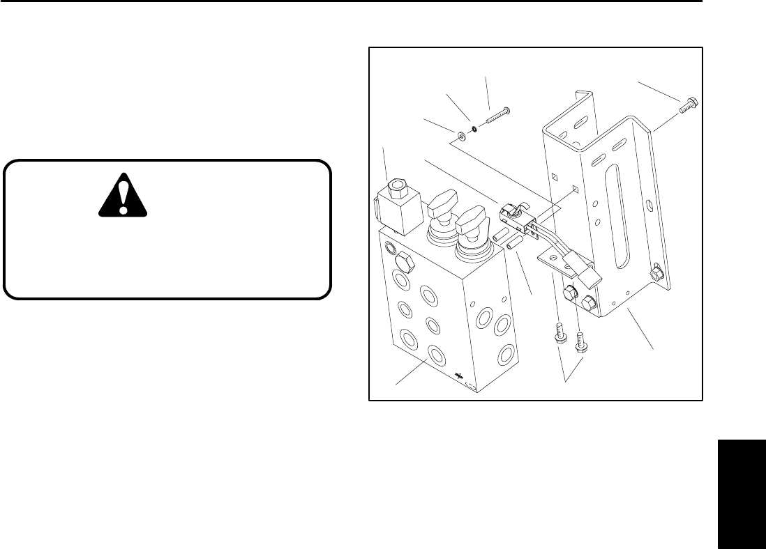
Removal (Fig. 57)
1. Before removing any parts from the hydraulic man-
ifold, park the machine on a level surface, engage the
parking brake, lower the cutting units and stop the en-
gine. Remove the key from the ignition switch.
CAUTION
Operate all hydraulic controls to relieve
system pressure and avoid injury from
pressurized hydraulic oil.
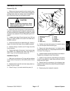
2. Raise and remove hood to get access to the man-
ifold.
Note: The ports on the manifold are marked for easy
identification of components. Example: R1 is the reel cir-
cuit relief valve and G1 is the test gauge connection port.
(See Hydraulic Schematics to identify the function of the
hydraulic lines and cartridge valves at each port loca-
tion).
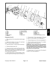
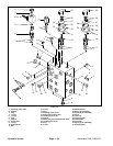
3. If necessary, the hydraulic manifold can be removed
(Figure 57):
A. Disconnect solenoid valve (9) and micro switch
(4) electrical connectors.
B. Clean manifold and hydraulic connections. Dis-
connect hydraulic lines. Label all connections for
reassembly.
C. Allow hydraulic lines to drain into a suitable con-
tainer. Put caps or plugs on disconnected hoses and
fittings to prevent contamination.
D. Remove cap screws (10) from the hydraulic
manifold.
E. Support hydraulic manifold (6) and remove
flange screws (7) from the hydraulic manifold. Re-
move hydraulic manifold from the cylinder support
bracket (8).
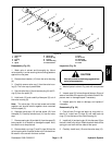
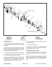
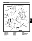
1. Screw
2. Lock washer
3. Flat washer
4. Micro switch
5. Spacer
6. Hydraulic manifold
7. Flange screw
8. Cylinder support bracket
9. Solenoid valve
10. Cap screw
Figure 57
3
1
2
4
5
8
7
6
9
10
Installation (Fig. 57)
1. Secure hydraulic manifold (6) to the cylinder sup-
port bracket (8) with cap screws (10) and flange screws
(7).
2. Make sure all hydraulic connections, ports, and fit-
tings are clean.
3. Connect hydraulic lines to the manifold. Tighten all
hydraulic fittings and connections.
4. Reconnect solenoid valve (9) and micro switch (4)
electrical connectors.
Hydraulic
System