


Reelmaster 2300–D/2600–D Hydraulic SystemPage 4 – 41
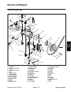
13. Remove retaining ring (37) from the bore on the
flange end of the housing assembly (15). Press the shaft
(31), shaft seal (36), and washer (35) from the housing
assembly.
14. Remove retaining ring (32), washer (35), thrust
bearing (34), second washer (35), and second retaining
ring (32) from the shaft (31).
15. Remove screws (7), trunnion cover (8), O–ring cov-
er (9), O–ring (10), washer (11), inner race (12), and
bearing (13). Remove screws (7), seal cover (16), shaft
seal (17), washer (11), and bearing (13).
16. Position camplate (20) to one side and remove from
the housing assembly (15).
Inspection
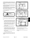
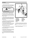
CAUTION
Use eye protection such as goggles when
using compressed air
1. Wash all parts in solvent. Dry parts with compressed
air.
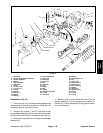
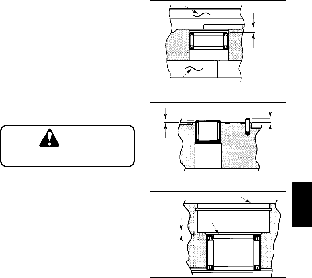
2. Inspect charge pump adapter assembly (see Fig.
25).
A. Check relief valve seat inside suction port. Make
sure that seat is smooth and free of burrs or other
defects. Relief valve spring must not be damaged.
B. Bearing needles must remain in bearing cage
and move freely. Verify that bearing depth on the
flange side meets the dimension in Figure 27.
C. Make sure gerotor pocket inside the pump is not
excessively scored.
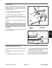
3. Inspect backplate assembly (25) (see Fig. 24).
A. Bearing needles must remain in bearing cage
and move freely. Verify that bearing height on the
numbered end meets the dimension in Figure 28.
B. Check that the roll pin is tight and meets the
height in Figure 28.
C. Replace entire assembly as a unit.
4. Inspect camplate assembly (20) (see Fig. 24).
There should be no signs of scoring on the piston shoe
surfaces.
Figure 27
GEROTOR POCKET
FLANGE
BEARING
DEPTH
0.090 to 0.100 in.
(2.54 to 2.89 mm)
Figure 28
BEARING
HEIGHT
ROLL PIN
HEIGHT
0.070 to 0.080 in.
(1.78 to 2.03 mm)
0.105 to 0.115 in.
(2.67 to 2.92 mm)
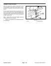
Figure 29
BEARING
DEPTH
NUMBERED END
FLANGE END OF HOUSING
0.062 to 0.078 in.
(1.57 to 1.98 mm)
5. Inspect housing assembly (15) (see Fig. 24).
A. Verify that bearing depth on the numbered end
meets the dimension in Figure 29.
B. Bearing needles must move freely and remain in
their cage.
Hydraulic
System
Hydraulic
System