


Reelmaster 2300–D/2600–D Hydraulic SystemPage 4 – 31
Procedure for Cross–over Relief Pressures
Check:
1. Make sure hydraulic oil is at normal operating tem-
perature by operating the machine for approximately 10
minutes. Make sure the hydraulic tank is full.
2. Make sure machine is parked on a level surface with
the cutting units lowered. Make sure engine is off and
parking brake is engaged. Back bedknives off all reels.
CAUTION
Operate all hydraulic controls to relieve
system pressure and avoid injury from
pressurized hydraulic oil.
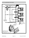
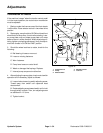
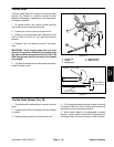
3. Clean manifold port G1. Remove cap and install
pressure gauge in manifold port G1.
4. Put a block of wood between the blades of the cut-
ting unit being tested to prevent the reel from rotating.
5. Make sure backlap knob on the valve block is in the
mow position.
6. One person should sit on the seat and operate the
machine while another person reads the tester. Start en-
gine and set throttle to full speed (3200 " 100 RPM).
CAUTION
Keep away from reels during test to pre-
vent personal injury from the rotating reel
blades.
CAUTION
Do not allow system pressure to exceed
1700 PSI. Shut off unit to prevent an over
pressure condition.
7. Engage cutting units. Observe pressure gauge.
Motor Position
Pressure Range (PSI)
Right Hand 1500 to 1600
Rear 1540 to 1640
Left Hand 1580 to 1680
8. Disengage cutting units and stop engine. If specifi-
cations are not met, replace cross–over relief. If specifi-
cations are met, remove block of wood from cutting unit
and repeat test on other reels in mow direction.
9. Remove test gauge and put cap on manifold port
G1.
IMPORTANT: Each reel motor has two cross over
reliefs. Test reliefs in the backlap direction only if
they are expected to be the problem. After testing
cross over reliefs in the backlap direction, make
sure the reel motor couplings are torqued (see Hy-
draulic Motor Removal and Installation of Chapter 7
– Cutting Units and Reel Motor in the Service and
Repair section).
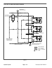
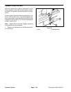
10. Clean left–hand reel motor and its hose connection
leading to manifold port M3. Disconnect hose connec-
tion and install pressure gauge with a T–connection be-
tween the hose connection and the motor.
11. Make sure backlap knob on the valve block is in the
backlap position.
12. One person should sit on the seat and operate the
machine while another person reads the gauge. Start
engine and move the throttle to full speed (3200 " 100
RPM).
CAUTION
Keep away from reels during test to pre-
vent personal injury from the rotating reel
blades.
CAUTION
Do not allow system pressure to exceed
1700 PSI. Shut off unit to prevent an over
pressure condition.
13. Engage cutting units. Observe pressure gauge.
Motor Position
Pressure Range (PSI)
Right Hand 1580 to 1680
Rear 1540 to 1640
Left Hand 1500 to 1600
14. Disengage cutting units and stop engine. If specifi-
cations are not met, the cross–over relief needs replac-
ing. Remove block of wood from cutting unit and repeat
test on other reels in the same direction of flow.
15. Remove test gauge and reconnect hose to motor.
Adjust bed bedknife to reel on all cutting units (see Ad-
justment section of Chapter 7 – Cutting Units.
Hydraulic
System