


Reelmaster 2300–D/2600–D Hydraulic SystemPage 4 – 39
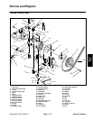
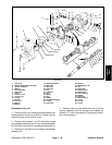
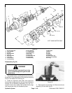
1. Cap screw
2. Charge pump adapter assembly
3. Gerotor assembly
4. Bearing
5. Valve assembly
6. Valve plate
7. Screw
8. Trunnion cover
9. O–ring cover
10. O–ring
11. Washer
12. Inner race
13. Bearing
14. Bearing
15. Housing assembly
16. Seal cover
17. Shaft seal
18. Dowel pin
19. Key
20. Camplate
21. Plug
22. Spring
23. Seat
24. Gasket
25. Backplate assembly
26. O–ring
27. Cap screw
28. Bearing
29. Rotating parts kit
30. Key
31. Drive shaft
32. Retaining ring
33. Bearing race
34. Thrust bearing
35. Washer
36. Shaft seal
37. Retaining ring
38. O–ring
39. O–ring
40. O–ring
Figure 24
28
29
30
31
32
33
35
36
37
1
2
3
4
5
6
78
14
15
16
17
18
19
20
40
22
23
24
18
25
26
27
9
10
11
12
13
13
11
7
33
34
32
21
39
38
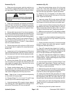
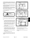
INNER RING
OUTER RING
COUPLER
KEY
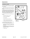
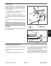
Disassembly (Fig. 24)
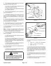
1. Position pump into a vise with protected jaws so the
charge pump drive shaft is pointed up. Clamp onto the
mounting flange of the traction pump.
2. Remove cap screws (1 and 27) and slide charge
pump adapter assembly (2) from the backplate assem-
bly (25) clear of the shaft (31) and gerotor assembly (3).
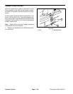
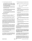
3. Remove O–ring (26) from the charge pump adapter
assembly (2).
4. Remove outer ring from either the inner ring of the
gerotor assembly (3) or the charge pump adapter as-
sembly (2). Further disassembly of the gerotor assem-
bly is not necessary.
Hydraulic
System