


Reelmaster 2300–D/2600–D
Page 5 – 21
Electrical System
Temperature Sending Unit
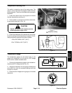
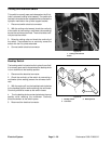
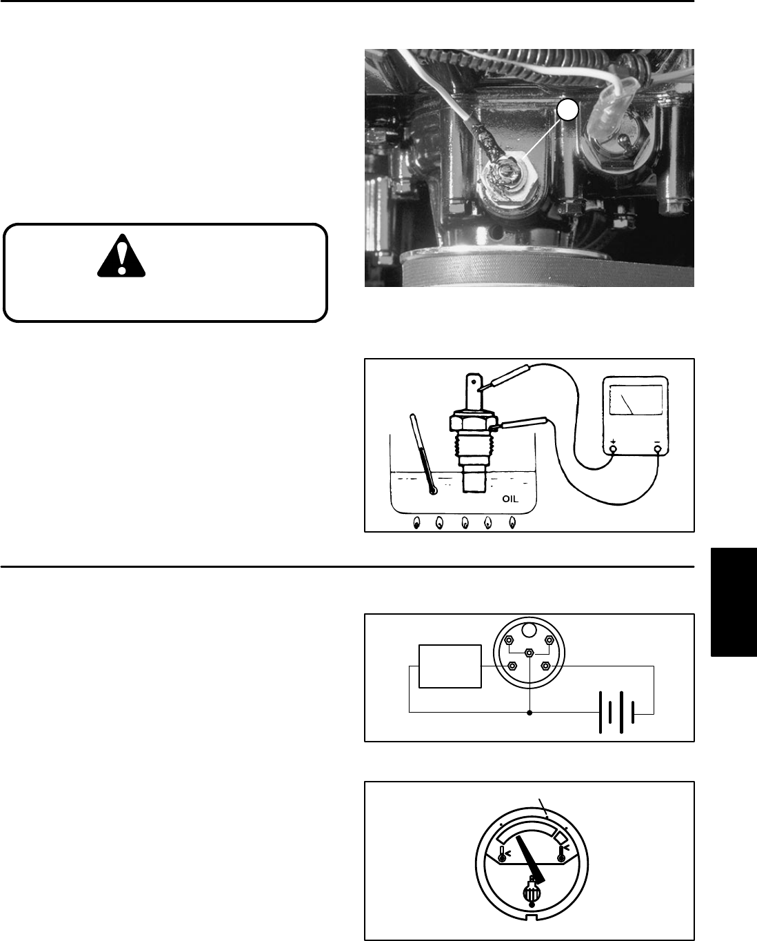
The switch is located on top of the water pump. The
pump is on the left end of the engine inside of the fan
pulley assembly. There is a white/black wire attached to
the switch.
1. Lower the coolant level in the engine and remove
the high temperature sending unit.
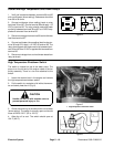
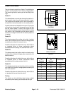
2. Put the switch in a container of oil with a thermome-
ter and slowly heat the oil (Fig. 12).
CAUTION
Handle the hot oil with extreme care to
prevent personal injury or fire.
3. Check the resistance of the sender with a multime-
ter (ohms setting) as the temperature increases. The fol-
lowing resistance readings should be indicated:
158 to 202 OHM at 130_F (54_C)
63 to 79 OHM at 180_F (82_C)
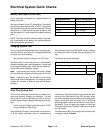
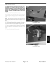
Figure 11
1
1. Temperature sending
unit
Figure 12
Temperature Gauge
The temperature gauge can be tested using a new
gauge as a substitute or by the use of a DC voltage
source and a variable resistance box.
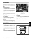
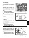
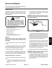
1. Connect the temperature gauge to the variable re-
sistance and DC voltage source (Fig. 13).
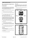
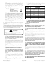
2. Adjust the resistance until the gauge needle points
to the 180_F tic mark; the resistance setting should be
from 63 to 79 ohms.
3. Disconnect the voltage source, gauge, and variable
resistance.
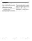
Figure 13
SI
G
+
–
VARIABLE
RESISTANCE
12 VDC
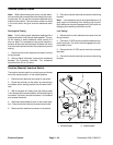
BACK
63 TO 79 OHMS
Figure 14
180_F (82_C) TIC MARK
FRONT
Electrical
System