


Reelmaster 2300–D/2600–DPage 7 – 14Cutting Units
Cutting Unit Removal and Installation (Fig. 15 through Fig. 18)
Remove Cutting Unit
1. Raise cutting units to relieve the tension on the
counterbalance springs.
2. Make sure traction unit is shut off and parking
brake is set.
Use caution when relieving tension or
tensioning springs as they are under
heavy load. Do not move lift lever, cutting
units can lower without the engine run-
ning.
WARNING
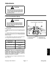
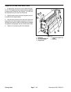
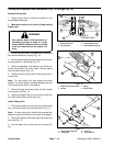
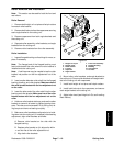
3. Loosen top cap screw. Put breaker bar in the square
hole and hold tension of spring (Fig. 15).
4. Remove bottom cap screw and slowly relieve the re-
maining tension on the spring (Fig. 15).
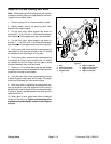
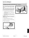
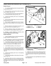
5. Remove capscrews, lock washers, and lift tab se-
curing the spring to the carrier frame. Remove spring
from the carrier frame (Fig. 16).
6. Note from which hole on the lift tab the spring is re-
moved from.
Note: On rear cutting unit, also remove the thrust
washer. The thrust washer is located between the rear
of the carrier frame and the flat washer.
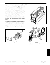
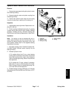
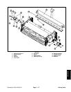
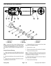
7. Remove flange head cap screw and flat washer
from the pivot rod (Fig. 17).
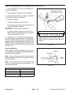
8. Disconnect tipper chain on front carrier frame (Fig.
18). Slide carrier frame off the pivot rod.
Install Cutting Unit
1. Place thrust washer on pivot rod (front cutting units
only), and slide carrier frame onto pivot rod (Fig. 17).
Note: On rear cutting unit, reinstall thrust washer be-
tween the rear of the carrier frame and the flat washer.
2. Secure flat washer and flange head cap screw onto
pivot rod (Fig. 17).
3. Connect tipper chain to the front carrier frame (Fig.
18).
3
4
1. Bottom capscrew
2. Top capscrew
3. Counterbalance arm
4. Counterbalance spring
2
1
Figure 15
INSERT
BREAKER BAR
2
3
1
1. Capscrew and lock washer
2. Lift tab
3. Spring
4. Carrier frame
4
Figure 16
4
1
1. Flange head capscrew
2. Flat washer
3. Pivot rod
4. Thrust washer
3
2
Figure 17