


Reelmaster 2300–D/2600–DHydraulic System Page 4 – 76
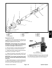
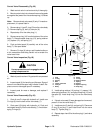
Control Valve Disassembly (Fig. 66)
1. Wash control valve in solvent and dry it thoroughly.
2. Mount control valve into a vise so the mounting pads
are against the jaws of the vice and snap ring (14) faces
up.
Note: Remove check valve seat (5) only if it needs re-
placement; it is press fitted in.
3. Remove plug (1) and O–ring (2) from the valve body
(7). Remove spring (3), ball (4), cam pin (6).
4. Repeat step 3 for the other plug (1).
5. Remove snap ring (14) from the bottom of the valve
body (7). Remove spool snap ring (13), spring retainer
(10), spacer (12), and spring (11).
6. Push and twist spool (8) carefully out of the valve
body (7). Set spool aside.
7. Remove O–rings (9) using a soft hooked scribe or
a thin screwdriver and being careful not to scratch the
valve bore finish.
Control Valve Inspection (Fig. 66)
CAUTION
Use eye protection such as goggles when
using compressed air
1. Wash all parts in solvent. Dry parts with compressed
air.
2. Inspect spool (8) for bending and flatness. Signs of
wear on one side of the spool may indicate it’s bent. Re-
place a worn or damaged spool if necessary.
3. Inspect parts for wear or damage, and replace if
necessary.
Control Valve Reassembly (Fig. 66)
1. Coat all new O–rings with hydraulic oil. Install new
O–rings (9) into the bore of the valve body (7).
2. Coat spool (8) lightly with hydraulic oil. Push and
twist spool carefully into the valve body (7). Avoid dam-
aging O–rings (9).
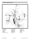
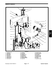
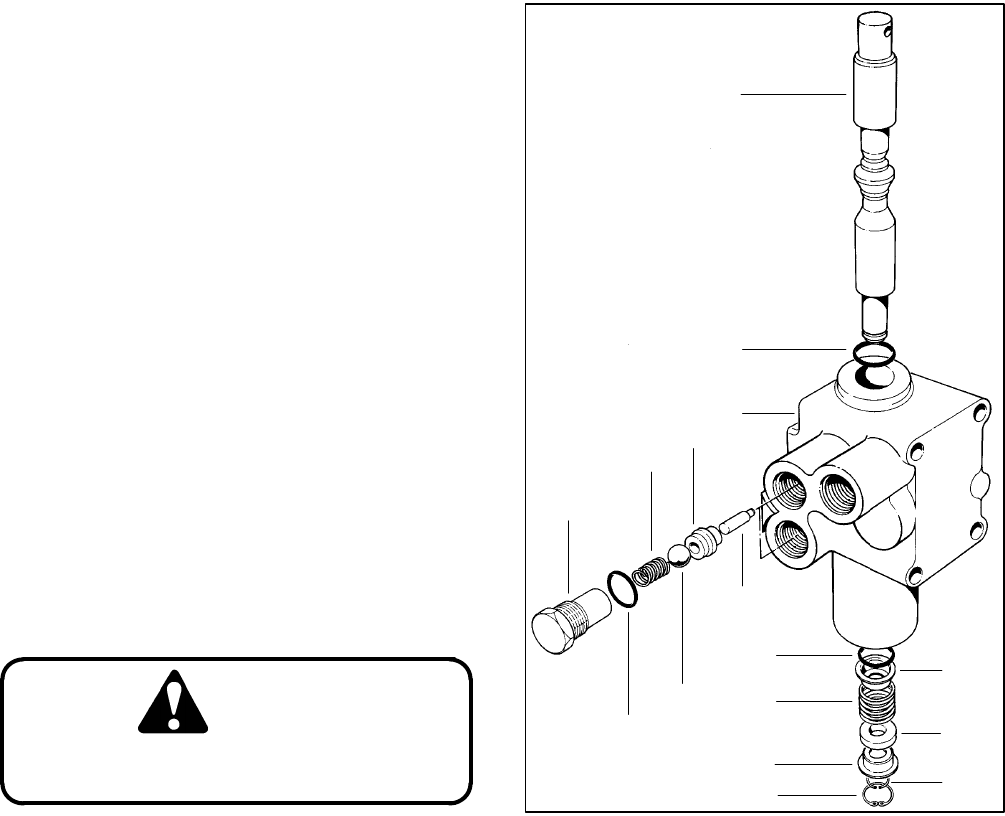
1. Plug
2. O–ring
3. Spring
4. Ball
5. Check valve seat
6. Cam pin
7. Body
8. Spool
9. O–ring
10. Spring retainer
11. Spring
12. Spacer
13. Spool snap ring
14. Snap ring
Figure 66
10
12
13
14
10
11
9
8
9
7
6
4
2
1
3
5
3. Install spring retainer (10), spring (11), spacer (12),
other spring retainer (10), and spool snap ring (13) onto
the spool (8). Install snap ring (14) into the valve body
(7).
4. If check valve seat (5) was damaged and removed,
press fit it into the valve body (7).
5. Install cam pin (6), ball (4), and spring (3). Place new
O–ring (2) on plug (1) and install them into the valve
body (7). Tighten plug (1).
6. Repeat steps 4 and 5 for the other plug (1) and valve
assembly.