


Reelmaster 2300–D/2600–D Hydraulic SystemPage 4 – 43
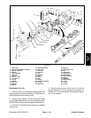
14. Install seat (23) and spring (22) into backplate (25).
Install new O–ring (40) and plug (21) into the backplate
assembly. Torque plug from 95 to 105 ft–lb (13.1 to 14.5
kg–m).
15. Install new O–rings (38 and 39) and valve assembly
(5) into the backplate assembly (25). Torque valve as-
sembly from 27 to 30 ft–lb (3.7 to 4.1 kg–m).
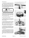
16. Coat valve plate (6) with light coat of petroleum jelly
on the steel side. Align the valve plate to the roll pin on
the backplate (25). Install steel side of the valve plate to
the backplate.
17. Install backplate assembly (25) to the housing as-
sembly (15). Make sure gasket (24), valve plate (6), and
dowel pins (18) stay in place.
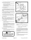
18. Install inner ring and coupler of gerotor assembly (3)
into the backplate assemble (25) so that the V–groove
on the coupler end enters the backplate assembly first.
Lubricate the inner ring of the gerotor.
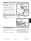
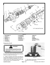
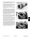
19. Reassemble charge pump adapter assembly (2) as
follows (see Fig. 25):
A. Install cup poppet, spring, and spring retainer
into the charge pump adapter assembly.
B. Torque retainer from 5 to 7 ft–lb (0.7 to 1.0
kg–m).
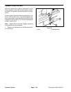
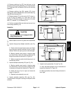
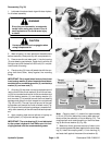
20. Coat O–ring (26) and outer ring of gerotor assembly
(3) with a light coat of petroleum jelly. Install O–ring and
outer ring onto the charge pump adapter assembly (2).
Install charge pump adapter plate onto the backplate as-
sembly (25). Make sure O–ring and outer ring of gerotor
assembly stay in place.
21. Secure charge pump adapter assembly (2) and
backplate assembly (25) to the housing assembly (15)
with cap screws (1 and 27). Torque cap screws from 17
to 20 ft–lb ( 2.3 to 22.8 kg–m).
Hydraulic
System