


Reelmaster 2300–D/2600–D Hydraulic SystemPage 4 – 57
Reel Motor Drive Pump
Removal (Fig. 53)
1. Before removing any parts from the hydraulic man-
ifold, park the machine on a level surface, engage the
parking brake, lower the cutting units and stop the en-
gine. Remove the key from the ignition switch.
CAUTION
Operate all hydraulic controls to relieve
system pressure and avoid injury from
pressurized hydraulic oil.
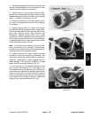
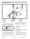
2. Clean reel motor drive pump (1) and hydraulic con-
nections. Install plug into the hydraulic reservoir. Label
all hose connections for reassembly purposes. Put caps
or plugs on any hydraulic lines or fittings left open or ex-
posed.
3. Loosen hose clamp (2) and remove hose (3) from
fitting (4). Allow hydraulic oil to drain from hose into a
suitable container.
4. Disconnect hose (5) from elbow fitting (6).. Allow hy-
draulic oil to drain from hose into a suitable container.
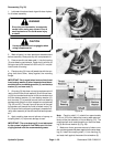
5. Remove fittings (4 and 6) and O–rings (8 and 9)
from the pump.
6. Support reel motor drive pump (1) and remove two
cap screws (10). Separate reel motor drive pump (1)
and O–ring (11) from the traction pump (12).
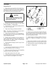
Installation (Fig. 53)
1. Make sure mounting and O–ring sealing surfaces
on reel motor drive pump (1) and traction pump (12) are
clean.
2. Replace all O–rings with new ones. Apply clean hy-
draulic oil to all O–rings.
3. Place O–ring (11) on reel motor drive pump (1).
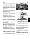
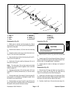
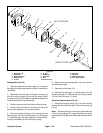
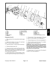
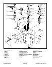
1. Reel motor drive pump
2. Hose clamp
3. Hose
4. Fitting
5. Hose
6. Elbow fitting
7. O–ring
8. O–ring
9. O–ring
10. Cap screw
11. O–ring
12. Traction pump
Figure 53
12
1
3
2
4
8
10
6
7
11
9
5
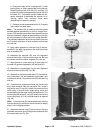
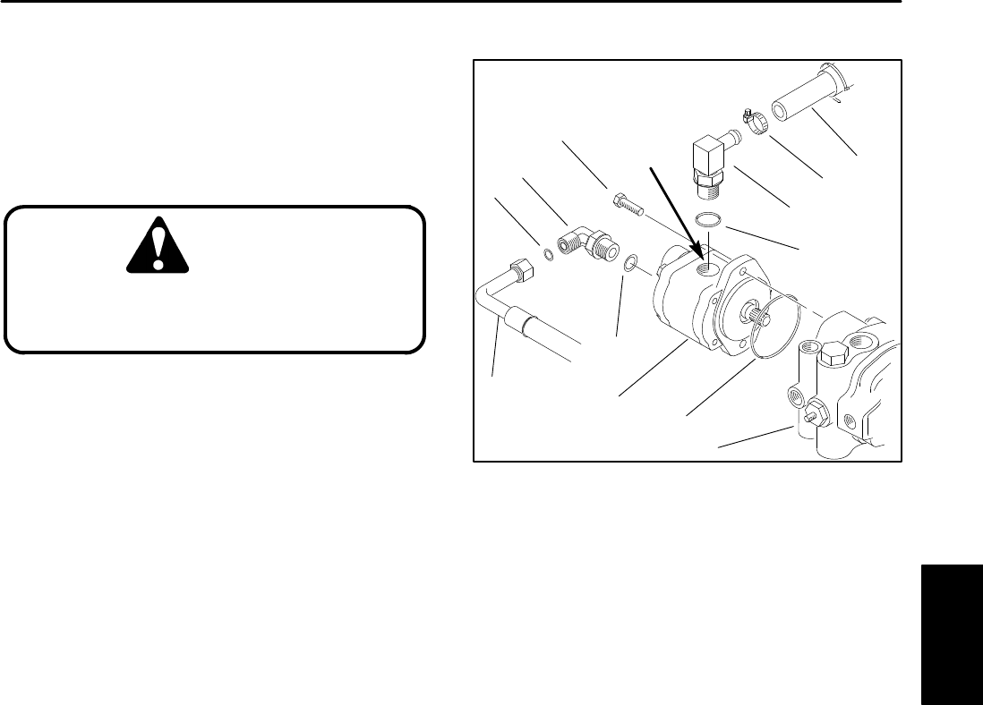
INLET PORT
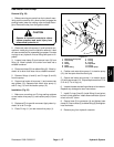
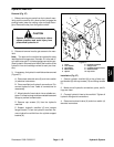
4. Position reel motor drive pump (1) to traction pump
(12); the inlet port should be facing up.
5. Secure reel motor drive pump (1) to traction pump
(12) with cap screws (10). Torque cap screws from 27 to
31 ft–lb (3.7 to 4.3 kg–m).
6. Inspect threads and sealing surfaces of connectors.
Replace any damaged or worn connectors.
7. Install O–rings (8 and 9). Install fitting (4) and orient
to the 2 o’clock position. Install elbow connector (6) and
orient to the 45_ down.
8. Secure hose (3) to connector (4) and tighten hose
clamp (2). Secure hose (5) to elbow fitting (6) and tighten
hose connector.
9. Remove plug from hydraulic reservoir.
Hydraulic
System