


Reelmaster 2300–D/2600–DHydraulic System Page 4 – 50
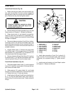
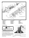
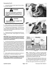
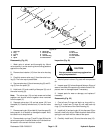
Reassembly (Fig. 32)
1. Lubricate all seals and seal rings with clean hydrau-
lic oil before assembly.
Since they are flammable, be extremely
careful when using any solvent. Even a
small explosion or fire could cause injury
or death.
WARNING
CAUTION
Use eye protection such as goggles when
using compressed air
2. Wash all parts in a clean petroleum–based solvent
before assembly. Blow parts dry with compressed air.
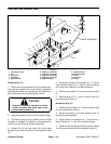
3. Press a new dirt and water seal (1) into the housing
(3) outer bearing counterbore. Press seal in with the lip
facing out and until the seal is 0.020 inch (0.51 mm) be-
low the end of housing.
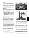
4. Place housing (3) into a soft jawed vise with the cou-
pling shaft bore down; clamp against the mounting
flange.
IMPORTANT: Early model wheel motors that do not
have backup washer (6) when inspected must be as-
sembled with a new backup washer (4), new backup
washer (6), and new seal (7).
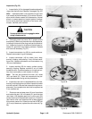
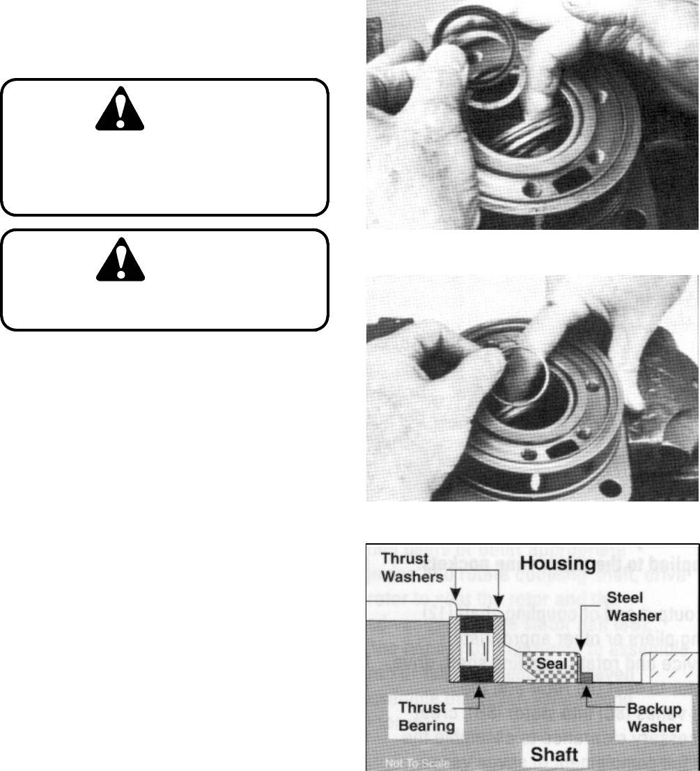
5. A housing (3) that does not require replacement will
require that the two thrust washers (8) and thrust bear-
ing (9) be unseated and vertical to the counterbore and
the new backup washer (4), new backup washer (6),
and new seal (7) be worked around the thrust bearing
package and placed into their respective counterbores
(Fig. 44 and 43). The seal lip must face out of the seal
counterbore and toward the inside of wheel motor (Fig.
45). Be sure the thrust bearing package is reseated cor-
rectly after assembly of the new seal and backup wash-
ers.
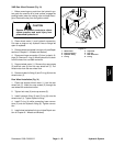
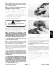
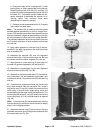
6. Apply masking tape around splines or keyway on
coupling shaft (11) to prevent damage to seal.
IMPORTANT: The outer bearing (2) is not lubricated
by the system’s hydraulic fluid. Make sure it is thor-
oughly packed with the recommended grease.
Figure 43
Figure 44
Figure 45
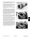
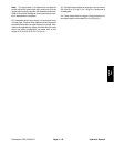
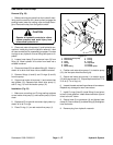
Note: Coupling shaft (11) should be approximately
0.10 inch (2.54 mm) below the housing wear plate sur-
face to allow the assembly of thrust bearing (12). The
coupling shaft must rotate smoothly on the thrust bear-
ing (9) and thrust washer (8) (Fig. 46).
7. Make sure that a generous amount of clean corro-
sion resistant grease has been applied to the outer bear-
ing (2). Install the coupling shaft (11) into housing (3),
and seat shaft against the second thrust washer (8).