


Reelmaster 2300–D/2600–D Page 3 – 19 Engine
J. Reconnect gray, red, and white leads to the en-
gine starter solenoid located on below the exhaust
manifold.
K. Reconnect battery ground to the traction clutch
side of the cylinder head or the left side of the cylin-
der block.
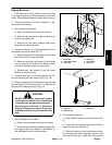
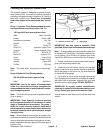
7. Reconnect throttle cable (Fig. 19).
A. Run throttle cable to engine (25).
B. Reinstall clevis pin (29), throttle tab (30), and
throttle cable to the engine governor lever. Reinstall
and lock cotter pin (31) to the clevis pin.
C. Install throttle cable into the throttle cable clamp
(26). Tighten cap screw (43).
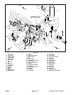
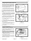
8. Reinstall exhaust system (Fig. 19).
A. Position muffler (14) and muffler gasket (45)
onto the exhaust manifold. Install capscrews (39)
and flat washers (11) to the muffler and exhaust
manifold. Tighten cap screws.
B. Reinstall cap screws (36) and washers (13) into
the muffler and right rear mount bracket (46).
C. Slide muffler tube through the U–clamp (17).
Connect muffler tube to the muffler. Tighten nut (20)
and U–clamp.
D. Reinstall muffler clamp (19) to the muffler (14)
and muffler tube (15).
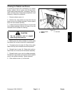
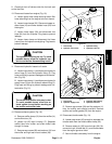
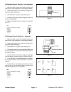
9. Reconnect hydraulic hoses from the oil cooler.
A. Unplug hydraulic hose (2) and hydraulic elbow
fitting (3). Connect hydraulic supply hose to the hy-
draulic elbow fitting. Tighten hose clamp (1) (Fig.
21).
B. Unplug hydraulic return hose (2) and hydraulic
fitting (3). Connect hydraulic return hose to the hy-
draulic fitting. Tighten hose clamp (1) (Fig. 20).
10. Connect hoses to the engine (Fig. 19).
A. Connect fuel hose (return) to the injector nozzle
piping and tighten hose clamp.
B. Unplug fuel hose (44). Connect fuel hose to the
lift pump and tighten hose clamp (38).
C. Connect upper radiator hose (18) and lower ra-
diator hose (24) to the engine. Tighten hose clamps
(23).
D. Connect air filter hose to the engine (25).
11. Open fuel shut–off valves under the fuel tank and on
the fuel filter.
12. Fill hydraulic reservoir with hydraulic fluid as de-
scribed in the General Information section of Chapter 4
– Hydraulic System. Check reservoir for leaks.
13. Add antifreeze to radiator as described in Checking
the Cooling System.
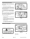
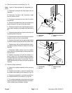
14. Slide the left foot rest (5) (Fig. 17) onto the adjusting
rod (2) (Fig. 18). Reinstall cap screws (3) and flange nut
(4) securing the left footrest (5) to the frame. Tighten cap
screws (Fig. 17).
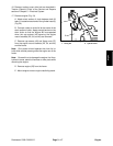
15. Connect adjusting rod to brake arm (3) Install and
lock cotter pin (1) to the adjusting rod (2) (Fig. 18).
16. Reinstall fender bracket (2) and left fender (1) to the
radiator side of the frame (Fig. 17).
A. Secure both cap screws (3) and left fender
bracket (2) to the frame.
B. Reinstall remaining cap screws (3) and flange
nuts (4) securing the fender to the fender bracket
and frame.
C. Secure cap screw (3) and flange nut (4) to the
left foot rest (5) and the left fender (1).
17. Replace traction pump drive belt as described in
Traction (Electric) Clutch of the Service and Repairs
section of Chapter 5 – Electrical System.
18. Adjust traction pump drive belt as described in the
Adjustment section of Chapter 4 – Hydraulic system.
19. Connect negative (–) and then positive (+) battery
cables at the battery.
20. Adjust hand brake as described in the Adjustment
section of Chapter 6 – Wheels and Brakes.
21. Adjust throttle linkage as described in the Adjust-
ment section of this chapter.
22. Bleed fuel system. See Bleeding the Fuel System.
23. Check oil level as described in Changing the Engine
OIl and Filter.
24. Replace access covers to the engine.
A. Reinstall left rear panel (radiator side) which
supports the instrument panel.
B. Reinstall right side panel which accesses the
traction pump drive belt.
C. Reinstall hood to the machine and close.
Engine