


Reelmaster 2300–D/2600–DHydraulic System Page 4 – 58
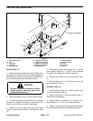
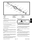
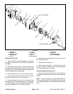
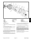
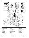
Figure 54
1
2
3
6
7
8
4
5
9
4
5
7
6
10
11
12
14
13
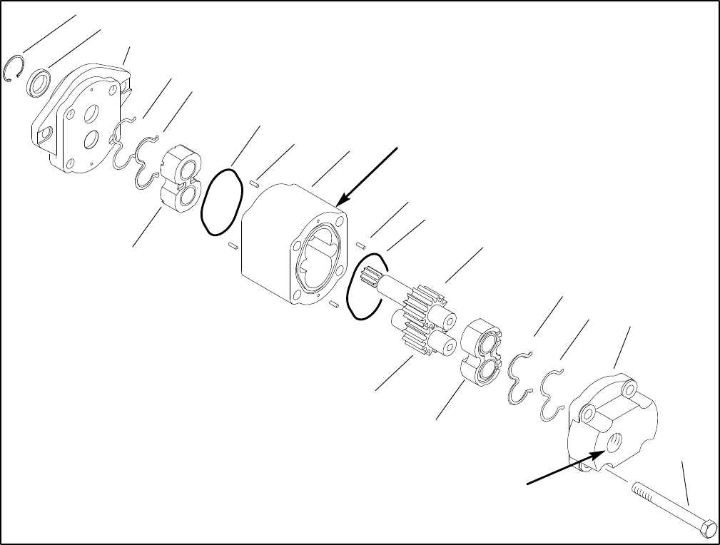
1. Retaining ring
2. Shaft seal
3. Mounting flange
4. Backup ring
5. E–seal
6. O–ring
7. Dowel pin
8. End cover
9. Bolt
10. Gear housing
11. Drive gear
12. Idler gear
13. Rear bearing block
14. Front bearing block
OUTLET PORT
INLET PORT SIDE
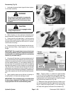
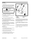
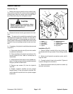
Disassembly (Fig. 54)
1. Tape the shaft end of the drive gear (11) to prevent
damaging the shaft seal when the shaft is removed or
reinstalled.
2. Matchmark the inlet side of the gear housing (10)
with the mounting flange (3) and the end cover (8) with
the gear housing (10) to make sure proper orientation of
these three parts during reassembly.
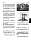
3. Position the pump with the drive end facing down.
4. Remove the four bolts (9). Lift off the end cover (8)
and and two dowel pins (7) and them aside.
5. Remove the gear housing (10) ensuring the rear
bearing block (13), front bearing block (14), drive gear
(11), and idler gear (12) remain together. Remove the re-
maining two dowel pins from the gear housing.
6. Remove the rear bearing block (13) from the drive
and idler gear shafts.
7. Remove the idler gear (12).
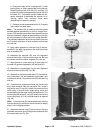
8. Remove the drive gear (11) shaft slowly from the
mounting flange (3). Remove the front bearing block
(14) from the drive gear (11) shaft.
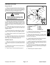
Shaft Seal Replacement (Fig. 54)
1. Place the mounting flange (3) on a clean working
surface with the shaft seal up (2). Remove the retaining
ring (1).
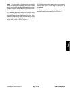
Note: Avoid scratching or marring the shaft seal bore
in the mounting flange (3). Large scratches may cause
the shaft seal (2) to leak around the outer diameter of the
seal.