


Reelmaster 2300–D/2600–DHydraulic System Page 4 – 52
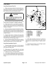
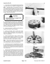
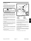
E. Grasp the output end of coupling shaft (11) with
locking pliers or other appropriate turning device.
Rotate coupling shaft, drive link (13), and rotor (19)
to seat the rotor and the assembled vanes (20) into
the stator (21). This rotation should create the nec-
essary clearance to assemble the seventh or re-
maining vanes. Use minimum force when
assembling the remaining vane(s).
F. Remove the two assembled bolts (14) if used to
retain stator and wear plate.
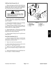
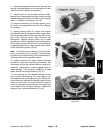
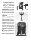
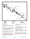
Note: The manifold (22) is made up of several plates
bonded together permanently to form an integral com-
ponent. The manifold surface that must contact the rotor
set has it’s series of irregular shaped cavities on the larg-
est circumference or circle around the inside diameter.
The polished impression left on the manifold by the rotor
set is another indication of which surface must contact
the rotor set.
15. Apply clean grease to a new seal ring (5) and as-
semble it in the seal ring groove in the rotor set contact
side of manifold (22).
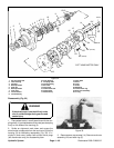
16. Assemble the manifold (22) over the alignment
studs and drive link (13) and onto the rotor set. Be sure
the correct manifold surface is against the rotor set.
17. Apply grease to a new seal ring (5) and insert it in
the seal ring groove exposed on the manifold (22).
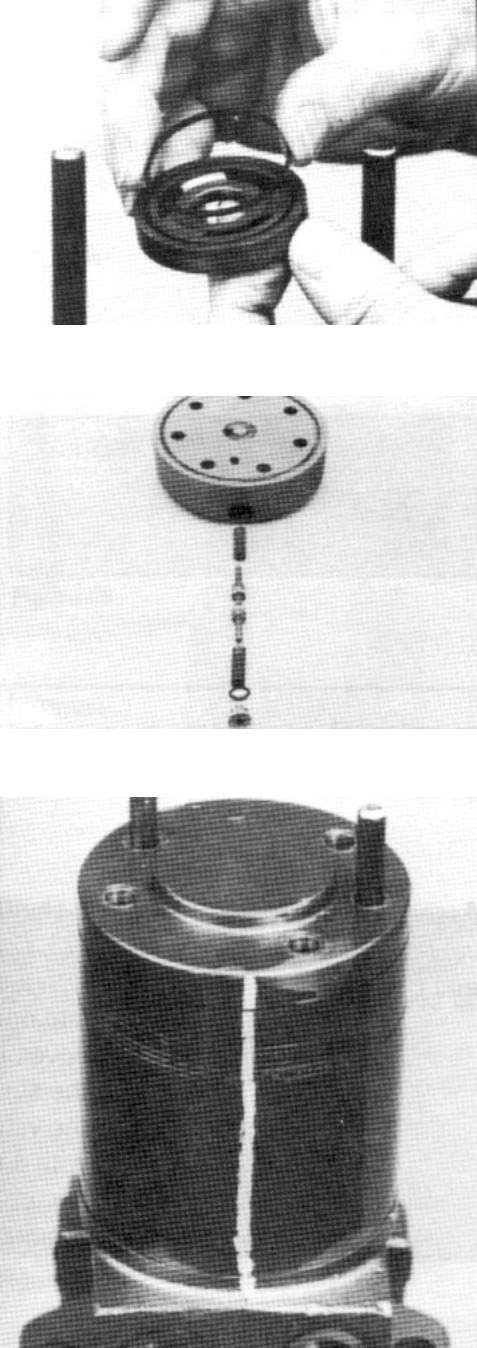
18. Assemble the commutator ring (6) over alignment
studs onto the manifold (22) (Fig. 48).
19. Assemble a new commutator seal (15) flat side up,
into commutator (16) and assemble commutator over
the end of drive link (13) onto manifold (22) with seal ring
side up.
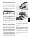
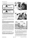
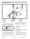
20. If shuttle valve components items (left–hand motor
only) were removed from the end cover (24), screw a
plug with a new O–ring (25), loosely into one end of the
valve cavity in the end cover. Insert spring, valve, and
second spring into the other end of the valve cavity. Turn
second plug with a new O–ring (25) loosely into the end
cover valve cavity. A 3/16–inch allen wrench is required
(Fig. 49).
Note: If the end cover (24) has a valve shuttle, use line
that was previously scribed on the end cover to radially
align it into its original position.
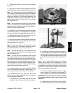
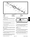
21. Assemble new seal ring (5) into end cover (24) and
assemble end cover over the alignment studs and onto
the commutator set (Fig. 50).
Figure 48
Figure 49
Figure 50