


Reelmaster 2300–D/2600–D
Page 3 – 18
Engine
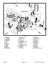
Engine Reinstallation
1. Make sure machine is parked on a level surface with
cutting units lowered, and key removed from the start
switch. Chock wheels to keep the machine from moving.
2. Make sure that all parts remove from the engine
during maintenance or rebuilding are reinstalled to the
engine.
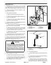
3. If mount brackets (22, 34, and 46) were removed re-
install them as follows (Fig. 19):
A. For front mount brackets (34), secure brackets
to the engine (25) with cap screws (36), lock wash-
ers (33) and washers (13). Torque cap screws from
34 to 42 ft–lb (4.7 to 5.8 kg–m).
B. For left rear mount bracket (22), secure bracket
to the engine (25) with two cap screws (36), lock
washers (33) and washers (13) through the left
holes. Leave the right holes open for the muffler.
Torque cap screws from 34 to 42 ft–lb (4.7 to 5.8
kg–m).
C. For right rear mount bracket (46), secure brack-
ets to the engine (25) with cap screws (36), lock
washers (33) and washers (13). Leave cap screws
loose enough so that the position of the bracket
can be adjusted after the engine is installed.
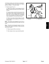
4. Reinstall engine (Fig. 19)
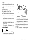
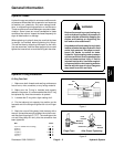
A. Attach short section of chain between both lift
tabs (1) located on each end of the cylinder head (2)
(Fig. 24)
B. Connect a hoist or chain fall at the center of the
short section of chain. Apply enough tension on the
short chain so that the engine will be supported
when the engine is removed from the engine re-
building stand. Remove engine from the engine re-
building stand.
Note: One person should operate chain fall or hoist
while another person guides the engine into the frame.
Note: Be careful not to damage the engine, fuel lines,
hydraulic hoses, electrical harness or other parts while
reinstalling the engine.
C. Reinstall engine (25) onto the frame. Make sure
fastener holes of the mount brackets (22, 34, and
46) are aligned with the holes on the frame.
D. Secure cap screws (42) and flange nuts (27) to
the mount brackets (22, 34, and 46) and frame.
E. On the right rear mount bracket (46), tighten cap
screws (36). Torque cap screws from 34 to 42 ft–lb
(4.7 to 5.8 kg–m).
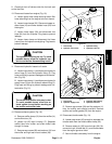
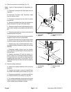
5. Reinstall radiator assembly.
A. Place radiator assembly down and then into the
engine to prevent the engine cooling fan from catch-
ing the radiator top and bottom shrouds.
B. Connect air filter hose extending from the engine
to the air cleaner. Tighten hose clamp.
C. Support the radiator assembly while installing
the fasteners.
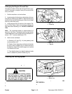
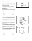
D. Install carriage bolts (1) and whiz nuts (2) to the
radiator bracket (3) and frame (4) (Fig. 23).
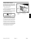
E. Install cap screws (1) and whiz nuts (2) to the ra-
diator rear bracket (3) and frame (4) (Fig. 22).
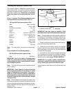
6. Reconnect electrical connections (Fig. 19).
A. Untie harness and hoses from the reservoir sup-
port brackets. Pull wiring harness and hydraulic
hoses into position; keep them from contacting
moving parts. Install cap screw (10) and flat washer
(11) to R–clamp (12) and tighten to cylinder head.
B. Reconnect connector with blue leads to the al-
ternator.
C. Reconnect connector with blue/white leads to
the traction clutch.
D. Reconnect connector to the front lift cylinder mi-
croswitch.
E. Reconnect white/black lead to the temperature
sender located on the top of the water pump.
F. Reconnect tan lead to the high temperature shut
down switch located on the water pump behind the
fan.
G. Reconnect purple lead to the fuel valve solenoid
located above the lift pump.
H. Reconnect brown lead to the oil pressure switch
located on the front of the cylinder head.
I. Reconnect white lead to the glow plugs located
on the front right side of the cylinder head.