


Reelmaster 2300–D/2600–DPage 7 – 24Cutting Units
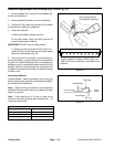
Preparing a Reel for Grinding
Note: Check to make sure reel bearings are in good
condition and properly adjusted before grinding reel.
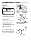
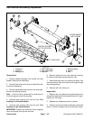
1. Remove bedbar assembly (see Bedbar Removal
and Installation).
2. Remove front roller and brackets (see Roller Re-
moval and Installation).
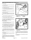
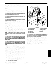
Note: Most reel grinders require that the rear roller
assembly be mounted to the cutting unit for proper sup-
port in the reel grinder. The rear roller must be parallel
to the reel shaft to remove taper when grinding, or the
cutting unit must be aligned so the grinding wheel will
travel parallel to the reel shaft. This will result in the the
reel being ground to the desired cylinder shape.
Note: When grinding, be careful to not overheat the
reel blades. Remove small amounts of material with
each pass of the grinder.
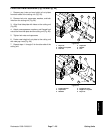
3. After completing grinding process:
A. Install front roller and brackets (see Roller Re-
moval and Installation).
B. Install bedbar assembly (see Bedbar Removal
and Installation).
C. Complete cutting unit set–up and adjustment se-
quence (see Adjustments section).
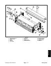
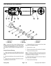
Reel Grinding Specifications
Nominal Reel Diameter
7I (178 mm)
Service Limit Reel Diameter
6.2I (158 mm)
Blade Relief Angle
30_
Relief Angle Range
20_ to 40_
Blade Land Width
.060I (1.5 mm)
Land Width Range
.050I to .090I (1.3 to 2.3 mm)
Max. Reel Taper
.060I (1.5 mm)
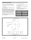
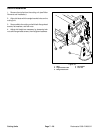
REEL DIAMETER TAPER = D
1
– D
2
D
1
D
2
BLADE RELIEF ANGLE
REEL DIAMETER
BLADE
LAND
WIDTH
Figure 27