


Reelmaster 2300–D/2600–DHydraulic System Page 4 – 72
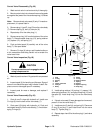
3. Put caps or plugs on disconnected hoses and fit-
tings to prevent contamination.
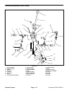
4. Remove cap screw (6) and ram pivot pin (7) from
pivot support (8). Slide lift pivot shaft (9) from pivot sup-
port.
5. Rotate lift cylinder (10) while swinging the lift cylin-
der down from the pivot support (8), so the hydraulic fit-
tings (3) and (4) are clear the exhaust pipe.
6. Remove cotter pin (11) from clevis pin (12). Support
lift cylinder (10) and slide clevis pin out of the lift arm (13)
removing flat washers (14).
7. Remove hydraulic fittings (3) and (4) and O–rings
(15) from the lift cylinder (10).
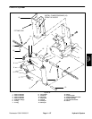
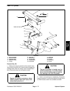
Installation (Fig. 63)
1. Coat new O–rings lightly with clean hydraulic oil.
Install hydraulic fittings (3) and (4) and new O–rings (15)
on the lift cylinder (10).
2. Position lift cylinder (10) inside pivot support (8).
Slide lift pivot shaft (9) through pivot support and lift cyl-
inder. Make sure lift pivot groove is aligned to accept the
ram pivot pin (7). Install ram pivot pin (7) and cap screw
(6).
3. Swing the lift cylinder (10) up so its clevis is posi-
tioned between the lift arm (13) slots. Slide a flat washer
(14) onto the clevis pin (12). Slide clevis pin through the
lift arm slots and the lift cylinder (10) clevis. Install re-
maining flat washer and then cotter pin (11) onto the cle-
vis pin.
4. Install hose connections (1 and 2) onto hydraulic fit-
tings (3 and 4). Tighten hose connections.
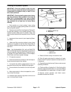
5. If rod clevis (14) has been removed, verify that the
distance between the carrier frame rollers (bumpers on
later models) and the foot step is about 1/4–inch (6 mm)
with the cutting units fully raised. Adjust rod clevis as
necessary. (Fig. 63)
A. Lower cutting units. Engage parking brake, stop
the engine, and remove key from the ignition switch.
B. Remove cotter pin (11) from clevis pin (12). Slide
clevis pin out of the lift arm (13) removing flat wash-
ers (14) (Fig. 64).
C. Separate rod clevis from lift arm (13) (Fig. 63).
D. Loosen jam nut (13) and adjust rod clevis (14) as
necessary (Fig. 64).Tighten jam nut.
E. Position rod clevis into lift arm (13) (Fig. 63).
F. Install clevis pin (12) and flat washers (14) into
the lift arm (13) and rod clevis. Secure clevis pin with
cotter pin (11) (Fig. 63).
G. Check distance between the carrier frame rollers
(bumpers on later models) and the foot step as de-
scribed above.
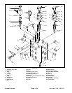
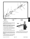
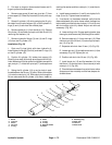
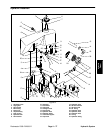
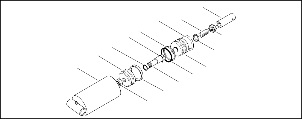
1. Barrel
2. Lock nut
3. Piston
4. Uni–ring
5. O–ring
6. Shaft
7. O–ring
8. O–ring
9. Backup washer
10. Head
11. Retaining ring
12. Dust seal
13. Jam nut
14. Rod clevis
Figure 64
1
3
5
7
9
11
6
13
12
10
8
6
4
2
14