


Reelmaster 2300–D/2600–D
Page 5 – 24
Electrical System
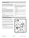
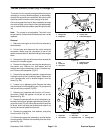
Traction (Electric) Clutch
Note: When disconnecting the clutch, use the electri-
cal connector that connects the clutch directly to the wir-
ing harness. Do not use the connector attached to the
traction clutch switch. This connector contains a diode
in the circuit which will give incorrect resistance read-
ings
Deenergized Testing
Note: Prior to taking small resistance readings with a
digital multimeter, short the test leads together. The me-
ter will display a small resistance value (usually 0.5
ohms or less). This resistance is due to the internal re-
sistance of the meter and test leads. Subtract this value
from from the measured value of the component you are
testing.
1. Disconnect the clutch electrical connector from the
wiring harness.
2. Using a digital multimeter, measure the resistance
between the connector terminals. The resistance
should be from 3.0 to 4.0 ohms.
3. Connect the clutch electrical connector to the wiring
harness.
Note: Low resistance may be accompanied by the 10
amp engine fuse blowing from drawing high current.
High resistance may be accompanied by the clutch not
engaging from drawing insufficient current.
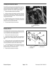
Live Testing
1. Disconnect the clutch electrical connector from the
wiring harness.
2. Connect a 12 VDC source across the electrical con-
nector terminals. The clutch should engage with a dis-
tinct audible ”click”.
3. Disconnect the 12 VDC source from the connector
terminals.
4. Connect the clutch electrical connector to the wiring
harness.
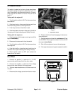
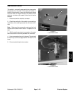
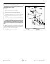
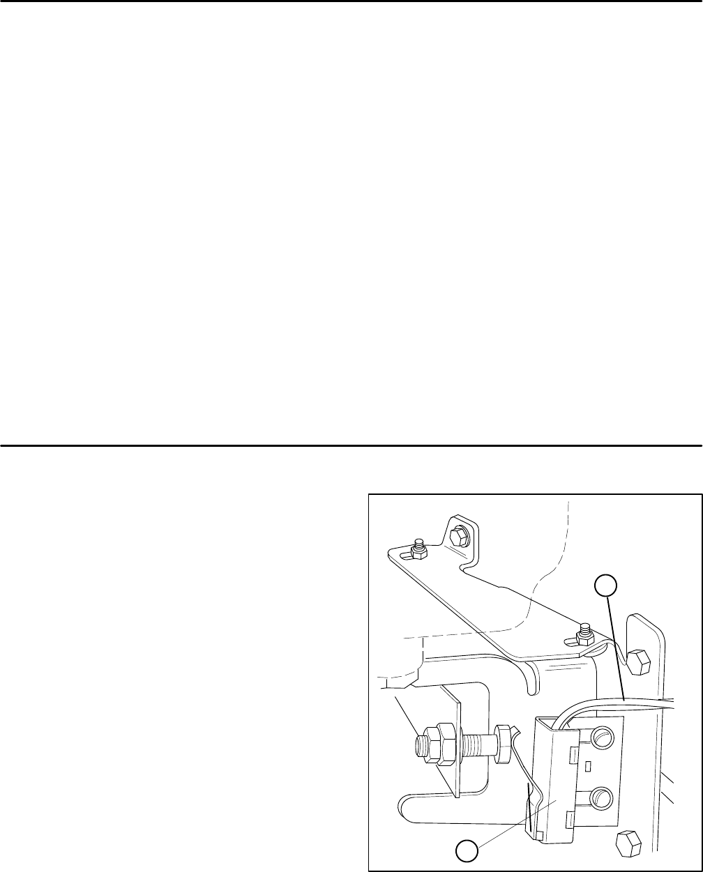
Traction (Neutral) Interlock Switch
The traction interlock switch is normally open and closes
when the traction pedal in in the neutral position.
1. Disconnect the electrical connector to the switch.
2. Check the continuity of the switch by connecting a
multimeter (ohms setting) across the connector termi-
nals.
3. With the engine off, slowly push the traction pedal
in the forward and reverse direction while watching the
multimeter. Continuity should be broken in the forward
and reverse directions.
4. Allow the traction pedal to return to the neutral posi-
tion. There should be continuity across the terminals.
5. Reconnect the electrical connector to the switch.
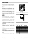
1. Connector leads 2. Interlock switch
Figure 20
1
2