


Reelmaster 2300–D/2600–DHydraulic System Page 4 – 66
B. Thread cartridge valve (1 or 14) carefully into the
applicable port (LC1 or R1). The valve should go in
easily without binding. Torque the valve to 35 ft–lb
(4.8 kg–m).
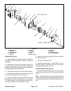
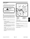
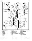
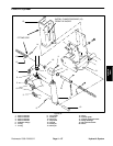
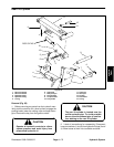
Spool (Flow Control and Two Position Directional)
Valves (Fig. 58)
1. Remove knob assembly:
A. Unscrew and remove knob (25). Remove both
jam nuts (26).
B. Slide off applicable indicator plate (27 or 31) be-
ing careful not to lose springs (24 or 30). Remove
spring.
C. Loosen set screw (29) and slide detent plate (28)
off the applicable spool valve (15 or 18) stem.
D. Remove the applicable locating plate with pin
(16 or 19) from the spool valve (15 or 18) stem and
manifold block (22).
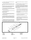
2. Make sure the manifold is clean before removing
the spool valve (15 or 18).
3. Remove the spool valve (15 or 18) and seal kit (7 or
17).
4. Visually inspect the port in the manifold (22) for
damage to the sealing surfaces, damaged threads, and
contamination.
5. Visually inspect spool valve (15 or 18) for damaged
sealing surfaces and contamination.
A. Contamination may cause valves to stick or
hang up. Contamination can become lodged in
small valve orifices or seal areas causing malfunc-
tion.
B. If sealing surfaces appear pitted or damaged,
the hydraulic system may be overheating or there
may be water in the system.
CAUTION
Use eye protection such as goggles when
using compressed air
6. If necessary, clean spool valve (15 or 18) using
clean mineral spirits. Submerge valve in clean mineral
spirits to flush out contamination. Particles as fine as tal-
cum powder can affect the operation of high pressure
hydraulic valves. Use compressed air for cleaning.
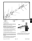
7. Reinstall the spool valve (15 or 18):
A. Lubricate new O–ring and backup ring of seal kit
(7 or 17) with clean hydraulic oil and install. The O–
ring and backup ring of seal kit must be arranged
properly on the spool valve (15 or 18) for proper op-
eration and sealing.
B. Thread spool valve (15 or 18) carefully into the
applicable port (FC1 or MD1). The valve should go
in easily without binding. Torque valve to 35 ft–lb
(4.8 kg–m).
8. Reinstall knob assembly:
A. Install applicable locating plate (16 or 19) so that
the pin seats into the locating hole.
B. Turn the threaded spool valve (15 or 18) stem
carefully clockwise until it stops.
C. Face detent plate (28) counterbore down.
Thread detent plate (28) down onto the valve stem
until it is stopped by the locating plate (16 or 19).
Turn detent plate (28) back counterclockwise 1/4
turn.
D. Center one detent plate hole over a locating
plate indentation. Drop a ball (23) into each hole,
then drop a spring (24 or 30) into each hole.
E. On spool (flow control) valve (15), place indica-
tor plate (27) over the detent plate (28). Make sure
the arrow points to the right at 45_.
F. On spool (two position directional) valve (18),
place indicator plate (31) over the detent plate (28).
Make sure the arrow points directly at the number 1
on the locating plate (16).
G. While pushing down on the indicator plate (27 or
31) and compressing the springs (24 or 30), thread
down a jam nut (26). While tightening the set screw
(29), tighten jam nut (26) at the same time using a
7/16 – inch wrench
H. Thread second jam nut (26) all the way down the
valve (15 or 18) stem. Apply ”Loctite 242” or equiva-
lent the valve stem threads. Screw knob (25) all the
way down until it hits the upper jam nut (26).
I. On spool (flow control) valve (15), turn knob (25)
counterclockwise until the arrow points at the num-
ber ”5”. Simultaneously tighten upper jam nut (26)
and turn knob so it is tight and the arrow is pointing at
the number ”1” on the locating plate (16).
J. On spool (two position directional) valve (18),
turn knob (25) counterclockwise so the arrow is 90_
with the back of the manifold body (22). Simulta-
neously tighten upper jam nut (26) and turn knob so
it is tight and the arrow is pointing 45_ to the right in
line with the indicator plate (31).