


Reelmaster 2300–D/2600–D
Page 5 – 26
Electrical System
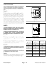
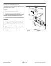
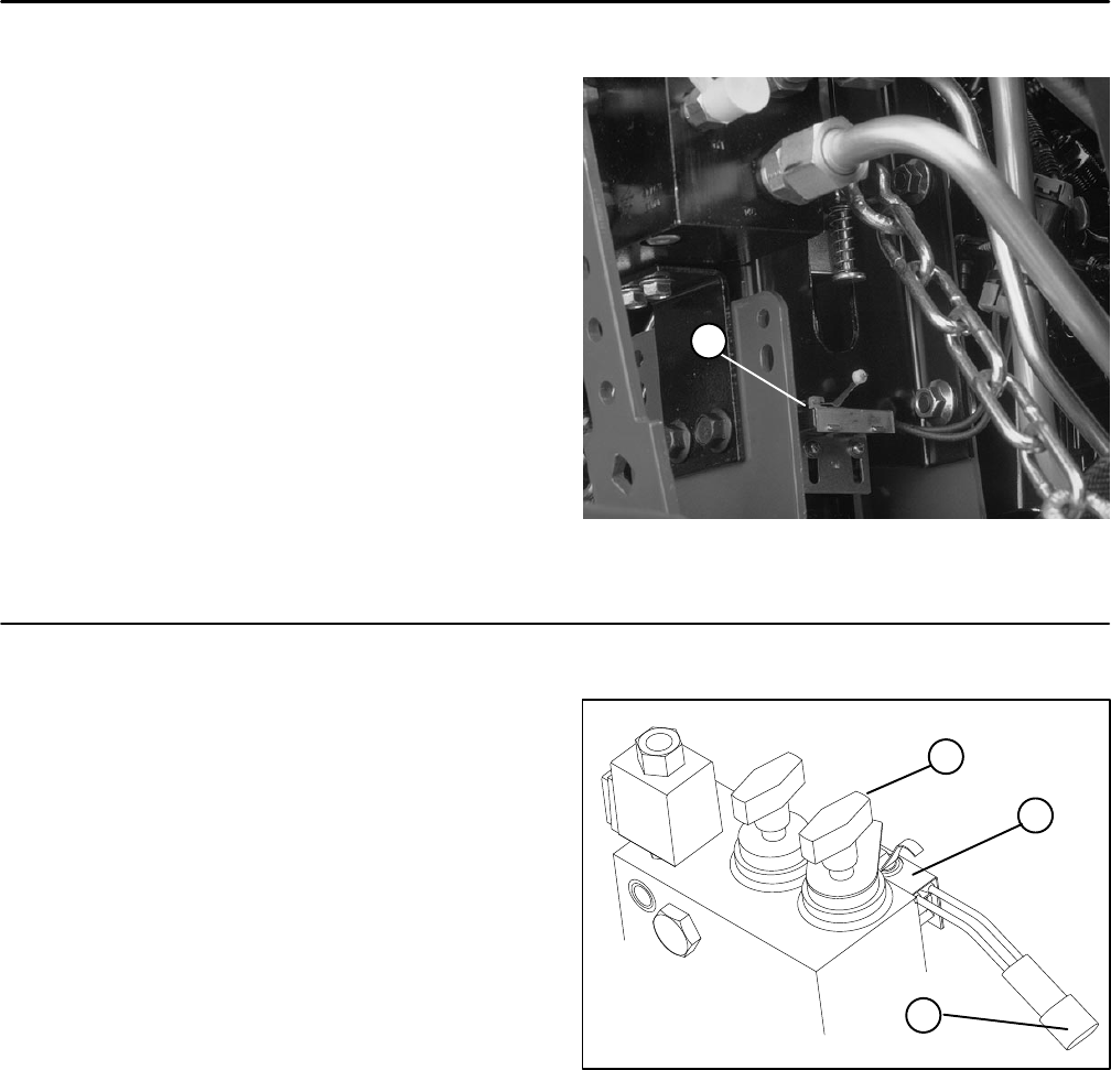
Cutting Unit Interlock Switch
This switch is normally open and closes when the lift cyl-
inder is retraced (cutting units lowered). The switch and
its electrical connector are located behind and below the
hydraulic manifold on the cylinder support bracket.
1. Disconnect switch electrical connector.
2. With the cutting units lowered, check the continuity
of the switch by connecting a multimeter (ohms setting)
across the connector terminals. There should be conti-
nuity across the switch.
3. Raise the cutting units and check the continuity of
the switch. There should be no continuity across the
switch with the lift cylinder extended.
4. Connect switch electrical connector.
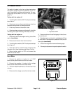
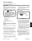
Figure 23
1
1. Cutting unit interlock
switch
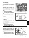
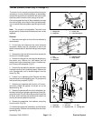
Backlap Switch
The backlap switch is located on the hydraulic manifold.
It is normally open and is closed when the backlap knob
is turn clockwise to the backlap position.
1. Disconnect the electrical connector.
2. Check the continuity of the switch by connecting a
multimeter (ohms setting) across the connector termi-
nals.
3. With the engine off, turn the backlap knob clockwise
to the backlap position while watching the multimeter.
Continuity should be made as the switch closes.
4. Turn the backlap knob counterclockwise to the mow
position while watching the multimeter. Continuity
should be broken as the switch opens.
5. Reconnect the electrical connector.
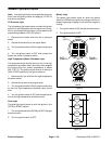
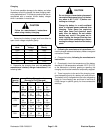
Figure 24
3
2
1
1. Backlap switch
2. Connector
3. Backlap knob