


Reelmaster 2300–D/2600–D Hydraulic SystemPage 4 – 35
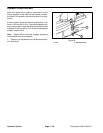
Traction Pedal
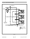
If traction pedal stop cam contacts the footrest when
pushed fully forward or maximum forward traction
speed is unattainable, an adjustment to the traction ped-
al linkage is required.
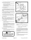
1. To expose traction rod, remove screws securing
right fender to frame and remove fender.
2. Loosen jam nuts on each end of traction rod.
3. Rotate rod until pedal stop cam clearance is from
0.03 to 0.09 inch (0.8 to 2.3 mm) with the pedal de-
pressed.
4. Retighten jam nuts securing traction rod adjust-
ment.
IMPORTANT: Verify reverse speed with one front
wheel off the ground in 2WD and the engine at high
idle. Reverse wheel speed should be from 120 to 140
RPM. Damage may result to rear motor if this speed
is exceeded.
5. The stop for reverse travel (under pedal) may be ad-
justed for slower travel.
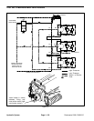
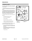
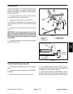
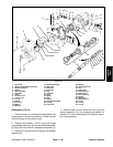
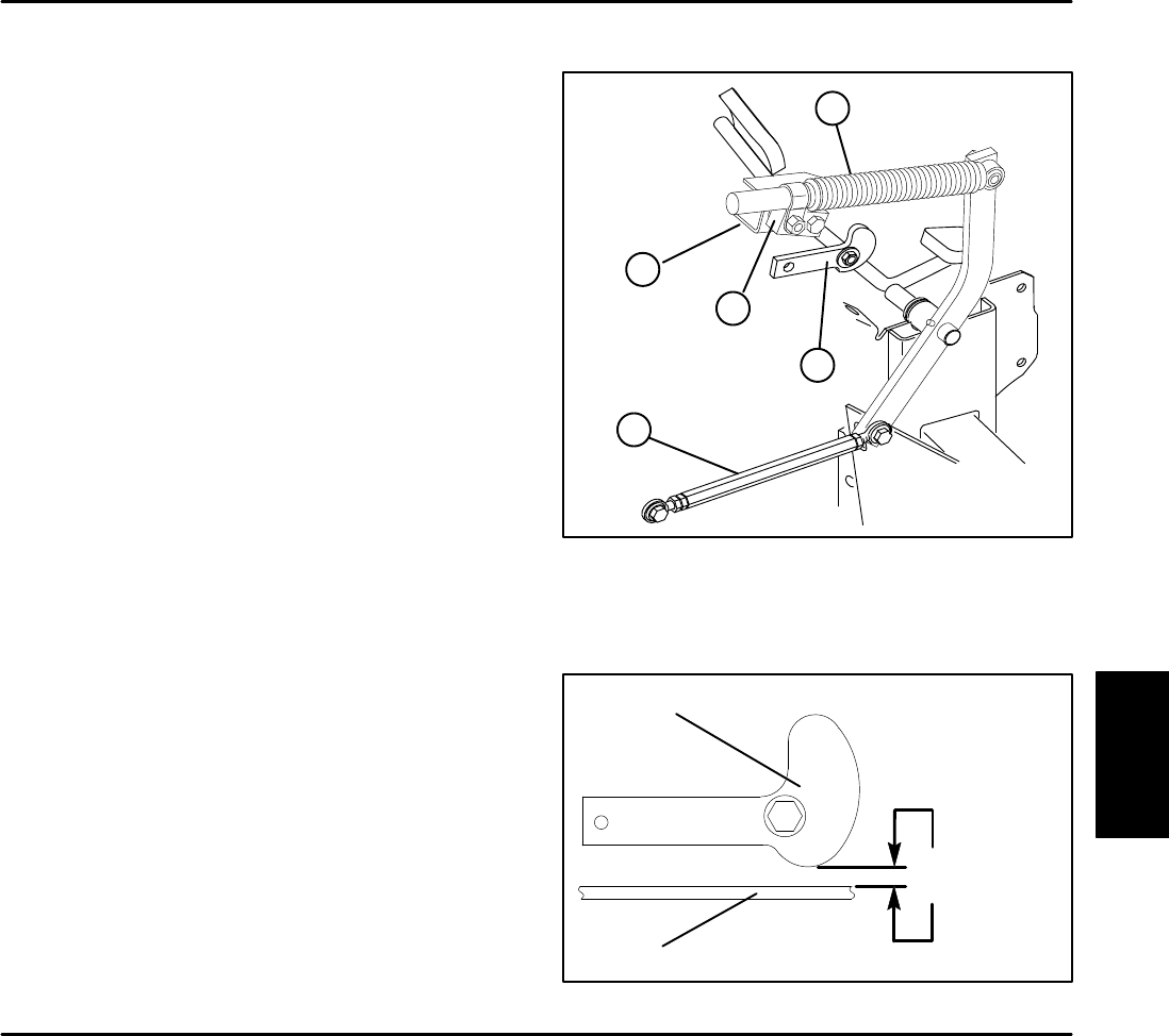
1. Traction rod
2. Damper
3. Damper pivot
4. Damper bracket
5. Pedal cam stop
Figure 20
1
2
3
4
5
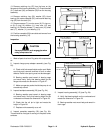
Figure 21
0.03 to 0.09 in.
(0.8 to 2.3 mm)
PEDAL STOP CAM
FOOT PLATE
Traction Pedal Damper (Fig. 20)
1. To expose traction pedal damper, remove right hand
panel.
2. Loosen locknut securing damper pivot to the damp-
er bracket.
3. Depress traction pedal fully forward and hold.
4. Fully compress damper and then release it allowing
it to extend 0.08 inch (2.0 mm). Tighten locknut securing
the damper pivot to the damper bracket.
5. When traction pedal is fully depressed in reverse
direction, traction pedal must contact reverse stop so
the damper does not act as the stop in either direction.
Hydraulic
System