


Reelmaster 2300–D/2600–DHydraulic System Page 4 – 8
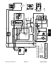
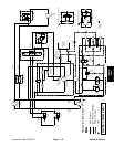
Hydraulic Flow Diagrams
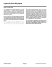
Raise Cutting Units
The charge pump is part of the traction pump and is di-
rectly coupled to it. It supplies hydraulic pressure for
raising and lowering cutting units and maintaining 100
to 150 PSI to the low pressure side of the traction circuit
(piston pump). The pump takes its suction through a fil-
ter from the reservoir.
During conditions of not lifting or lowering cutting units,
flow from the charge pump goes to the control valve and
is by–passed (control valve position not shown) directly
to the suction of the piston pump and the charge relief
valve.
When the cutting units are to be raised, the control valve
spool is positioned down and flow is directed out the top
of the control valve to the lower and outer portions of the
lift cylinders. Hydraulic pressure against the cylinder
pistons pushes the shafts out. At the same time, the pis-
tons push the hydraulic fluid in the upper and inner por-
tions of the lift cylinders out and through the control valve
to the piston pump suction. When the control valve lever
is released, spring action returns the spool to the center
position and by–passes flow back to the piston pump
suction. Lift cylinder movement is stopped. The cylinder
position is locked in place since there is no complete cir-
cuit of flow to and from the lift cylinders.
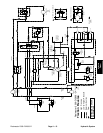
Circuit operation for lowering the lift cylinders is similar
to raising them. However, the control valve spool is
shifted up and flow is reversed to and from the lift cylin-
ders, thus moving the cutting units down.