


Reelmaster 2300–D/2600–D Hydraulic SystemPage 4 – 75
1. Before removing any parts from the control lift valve
assembly, park the machine on a level surface, engage
the parking brake, lower the cutting units and stop the
engine. Remove the key from the ignition switch.
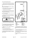
CAUTION
Operate all hydraulic controls to relieve
system pressure and avoid injury from
pressurized hydraulic oil.
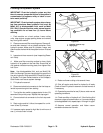
2. Remove side panels lift hood to gain access to the
control valve and relief valve.
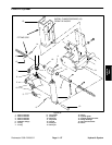
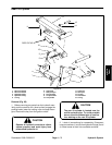
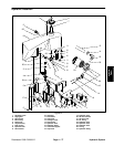
Control Valve Removal (Fig. 65)
1. Disconnect hose connections (1, 11, 14, and 15)
from hydraulic fittings (2 and 13). Allow hoses to drain
to a suitable container.
2. Remove lock nuts (5 and 16). Slide cap screw (4)
and washer (3) from the control valve (9).
3. Slide control valve (9) from the support bracket (17)
and remove from the unit.
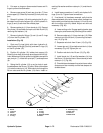
4. Unsnap and remove connecting link assembly (8).
Remove valve lever (6) from the control valve (9).
5. Disconnect tube (18) from hydraulic fitting (2). Dis-
connect tube (12) from hydraulic fitting (10).
6. Remove hydraulic fittings (2, 10, and 13) and O–
rings (21 and 23) from the control valve (9).
Control Valve Installation (Fig. 65)
1. Install O–rings (21 and 23) and hydraulic fittings (2,
10, and 13) to the control valve (9).
2. Install tube (12) to hydraulic fitting (10). Connect
tube (18) to hydraulic fitting (24).
3. Install valve lever (6) to the control valve (9) by
snapping the connecting link assembly (8) to the valve
lever and control valve.
4. Position control valve (9) into unit and slide onto
support bracket (17).
5. Slide cap screw (4) into control valve (9) and install
washer (3). Secure lock nuts (5 and 16).
6. Connect hose connections (1, 11, 14, and 15) to hy-
draulic fittings (2 and 13) and tighten connections.
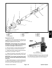
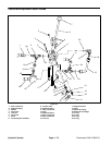
Relief Valve Removal (Fig. 65)
Note: This procedure may be used if only the relief
valve needs removal from the unit.
1. Disconnect hose connection (11) from hydraulic fit-
ting (2). Allow hose to drain to a suitable container.
2. Disconnect tube (18) from hydraulic fitting (2). Allow
fitting to drain to a suitable container.
3. Remove relief valve body (19) and hydraulic fitting
(2) from tube (12).
4. Remove hydraulic fitting (2), tube (18) and both O–
rings (23) from the relief valve body (19).
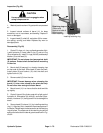
Relief Valve Installation (Fig. 65)
Note: This procedure may be used if only the relief
valve has been removed from the unit.
1. Install hydraulic fitting (2) and O–ring (23) to the re-
lief valve body (19).
2. Install tube (18) and O–ring (23) to the relief valve
body (19).
3. Set relief valve body (19) and attachments into the
unit.
4. Connect tube (18) to hydraulic fitting (2).
5. Connect tube (12) to hydraulic fitting (2).
6. Connect hose connection (11) to hydraulic fitting
(2).
Hydraulic
System