


Reelmaster 2300–D/2600–DHydraulic System Page 4 – 40
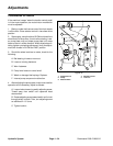
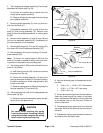
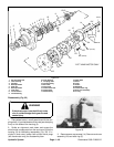
5. The charge pump adapter assembly (2) can be dis-
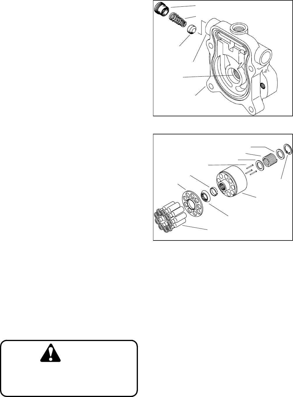
assembled as follows (see Fig. 25):
A. Unscrew and remove spring retainer from the
charge pump adapter assembly.
B. Remove spring and cup poppet from the charge
pump adapter assembly.
6. Remove gerotor assembly (3) inner ring and cou-
pler from the shaft (31).
7. Lift backplate assembly (25) up and off from the
shaft (31) and housing assembly (15). Remove valve
plate (6) from the backplate assembly or rotating parts
kit (29).
8. Remove valve assembly (5) and O–rings (38 and
39) from the backplate assembly (25). Disassembly of
the valve assembly is not necessary.
9. Remove both plugs (21), O–rings (40), spring (22),
and seats (23) from the backplate assembly (25).
10. Remove gasket (24) from the housing (15) or back-
plate assembly (25).
Note: To remove the rotating parts kit (29) from the
shaft (31), a table or workbench with a hole in the work-
ing surface is required for the protruding shaft.
11. The rotating parts kit (29) can be removed from the
shaft (31) as follows:
A. Hold rotating parts kit (29) in place and remove
the pump from the vise.
B. Position the housing assembly (15) end of the
pump up and lower the shaft (31) through the hole in
the table or workbench. Allow rotating parts kit (29)
to rest on the table.
C. Remove rotating parts kit (29) by lifting away the
housing assembly (15) and shaft (31).
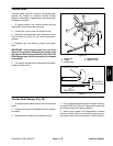
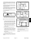
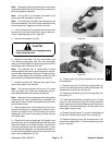
12. The rotating parts kit (29) can be disassembled as
follows (see Fig. 26):
A. Remove nine piston assemblies, spider, and spi-
der pivot from the piston block.
CAUTION
Be careful when removing the spring
from the piston block; the spring is highly
compressed. Safely compress the spring
before removing the retaining ring.
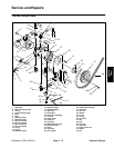
Figure 25
SPRING RETAINER
SPRING
CUP POPPET
CHARGE PUMP
ADAPTER ASSEMBLY
BEARING
SUCTION PORT
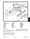
Figure 26
PISTON ASSEMBLIES
SPIDER
SPIDER PIVOT
RETAINER
PISTON BLOCK
PINS
WASHER
SPRING
WASHER
RETAINING RING
CAMPLATE END
VALVE PLATE END
B. Use the following parts to disassemble the pis-
ton block:
2 5/16 in. I.D. 15/16 in. O.D. flat washers
1 5/16 in. 2–7/8 in. N.C. cap screw
1 5/16 in. N.C. nut
C. Place cap screw through one of the flat washers.
Insert cap screw through the center of the piston
block. Install second flat washer onto the capscrew
so the washer rests on the three pins. Screw nut
onto the cap screw.
D. Compress spring by tightening the nut onto the
cap screw. Remove the retaining ring from the pis-
ton block.
E. Slide washer, spring, second washer, three pins,
and retainer from the piston block.