


Reelmaster 2300–D/2600–D Hydraulic SystemPage 4 – 59
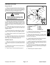
2. Remove the shaft seal (2). Clean any contamination
from the seal bore.
3. Place a new shaft seal (2) with the part number side
up into the seal bore. Apply uniform pressure to the face
of the shaft seal while pressing it into the bore. This
method should prevent damage or misalignment of the
seal in the bore.
4. Install new retaining ring (1) into the mounting
flange.
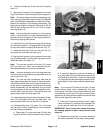
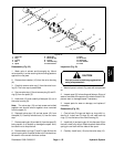
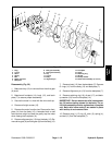
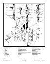
E–seal and Backup Ring Replacement (Fig. 54)
1. Place the front bearing block (14) on a clean sur-
face. Remove the old backup ring (4) and E–seal (5).
Clean any contamination from the E–seal groove.
2. Apply a light coat of petroleum jelly in the E–seal
groove of the front bearing block (14) and on the flat side
of the E–seal (5) to help keep the seals in place during
assembly.
3. Place the E–seal (5) with its flat side up into the seal
groove on the front bearing block (14). Place the backup
ring (4) into the groove made by the E–seal and bearing
block. Make sure the notches in the center of the backup
ring and E–seal line up so that the backup ring sits flush
with the E–seal.
4. Repeat the above steps for the rear bearing block.
O–ring Replacement (Fig. 54)
1. Remove the old O–rings (6) from the gear housing.
Clean any contamination from the O–ring groove.
2. Apply a light coat of petroleum jelly in the O–ring
grooves of the gear housing (10). Place a new O–ring (6)
in each groove.
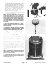
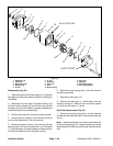
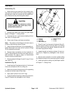
Reassembly (Fig. 54)
1. Place the mounting flange (3) with the shaft seal (2)
side down onto a clean working surface. Make sure that
the back side of the mounting flange is free of any con-
tamination.
2. Place the front bearing block (14) with its seal side
down onto the mounting flange (3). The open side of the
E–seal (5) must point away from the matchmark on the
inlet side of the mounting flange.
3. Apply a light coating of oil to the exposed face of the
front bearing block (14). Make sure the tape is on the
shaft end of the drive gear (10). Insert the shaft end of
the drive gear (11) slowly through the front bearing block
(14) and the shaft seal (2) being careful not to damage
the shaft seal.
4. Place the shaft of the idler gear (12) into the remain-
ing position of the front bearing block (14). Apply a light
coating of oil the back face of the drive and idler gears.
5. Place the rear bearing block (13) with the seal side
on the drive and idler gear shaft ends. Make sure that the
open side of the E–seal (5) is pointing towards the inlet
of the pump.
6. Install the two dowel pins (7) into the mounting
flange (3).
7. Align the matchmarks on the gear housing (10) and
mounting flange (3). Place the gear housing with the
mounting flange side down and the inlet port on the open
side of the E–seal (5) over the rear bearing block (13).
Slide the gear housing down over the gears and front
bearing block (14).
8. Make sure the rear bearing block (13) face sits just
below the back face of the gear housing (3). If the rear
bearing block sits higher than the rear face of the gear
housing, remove the gear housing. Check that the E–
seal (5), backup ring (4), or O–ring (6) did not shift out
of place during assembly.
9. Place the remaining two dowel pins (7) into the rear
of the gear housing (3). Align matchmarks and set end
cover (8) on the rear of the gear housing.
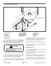
10. Insert the four bolts (9) through the bolt holes in the
end cover (8) and gear housing (3). Hand tighten each
bolt and torque to 40 ft–lb (5.5 kg–m).
11. Place a small amount of oil in the inlet of the pump.
rotate the drive shaft away from the inlet one revolution.
If the drive shaft binds, disassemble the pump and then
reassemble it. The pump is ready for use.
Hydraulic
System