


Reelmaster 2300–D/2600–D Hydraulic SystemPage 4 – 73
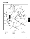
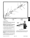
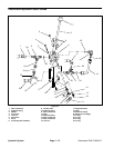
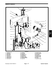
Disassembly (Fig. 64)
1. Remove oil from cylinder into a drain pan by slowly
pumping the cylinder shaft (6). Plug both ports and clean
the outside of the lift cylinder.
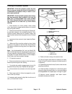
IMPORTANT: Prevent damage when clamping the
lift cylinder into a vise; clamp on the pivot end only.
Do not close vise enough to distort the barrel (1).
2. Mount lift cylinder in a vise so that the shaft (6) end
tilts up slightly.
3. Remove retaining ring (11) from the barrel (1).
4. Grasp clevis rod (14); extract shaft (6), head (10),
and piston (3) by carefully twisting and pulling on the
shaft out from the barrel (1).
IMPORTANT: Do not clamp vise jaws against shaft
surface. Protect shaft surface before mounting in
the vise.
5. Mount shaft (6) securely in a vise. Remove locknut
(2) and piston (3) from the shaft. Slide head (10) off the
shaft.
6. Remove and discard uni–ring (4) and O–ring (5)
from the piston (3). Remove and discard dust seal (12),
backup washer (9), and O–rings (7 and 8) from the head
(10).
Note: If the rod clevis (14) is to be removed from the
shaft (6), note the number of threads exposed between
the jam nut (13) and the smooth surface of the shaft to
help reassembly.
7. Loosen jam nut (13) and remove clevis if necessary.
Inspection (Fig. 64)
CAUTION
Use eye protection such as goggles when
using compressed air
1. Wash all parts in solvent. Dry parts with compressed
air.
2. Inspect internal surface of barrel (1) for deep
scratches, out–of–roundness, and bending. Replace if
worn or damaged.
3. Inspect head (10), shaft (6), and piston (3) for ex-
cessive pitting, scoring, and wear. Replace any worn or
damaged parts.
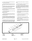
Reassembly (Fig. 64)
1. Coat new dust seal, uni–ring, backup washer, and
all O–rings lightly with hydraulic oil. Install new O–ring
(5) and uni–ring (4) to the piston (3). Install O–rings (7)
and (8) and backup washer (9) to the head (10). Press
dust seal (12) into head (10).
IMPORTANT: Do not clamp vise jaws against shaft
(6) surface. Protect shaft surface before mounting
in the vise.
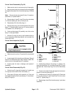
2. Mount shaft (6) securely in a vise. Adjust clevis (14)
and jam nut (13) so the number of threads exposed be-
tween the jam nut (13) and the smooth surface of the
shaft is the same as noted during disassembly. The jam
nut must be tight against rod clevis for this adjustment.
3. Coat shaft (6) lightly with hydraulic oil. Slide head
(10) onto the shaft being careful not to damage O–ring
(7) and dust seal (12).
4. Install piston (3) onto the shaft being careful not to
damage O–ring (5). Install locknut (2) onto the shaft and
tighten.
5. Remove shaft (6) from the vise.
IMPORTANT: Prevent damage when clamping the
barrel (1) into a vise; clamp on the pivot end only. Do
not close vise enough to distort barrel.
6. Mount barrel (1) in a vise so that the shaft end tilts
up slightly.
7. Coat all internal lift cylinder parts with a light coat of
hydraulic oil. Slide piston (3), shaft (6), and head (10) as-
sembly into barrel (1) being careful not to damage the
seals.
8. Secure head (3) in barrel (11) by installing retaining
ring (1) into barrel groove.
Hydraulic
System