


Reelmaster 2300–D/2600–D Hydraulic SystemPage 4 – 51
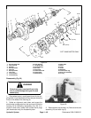
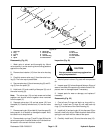
8. Install thrust bearing (12) onto the end of coupling
shaft (11).
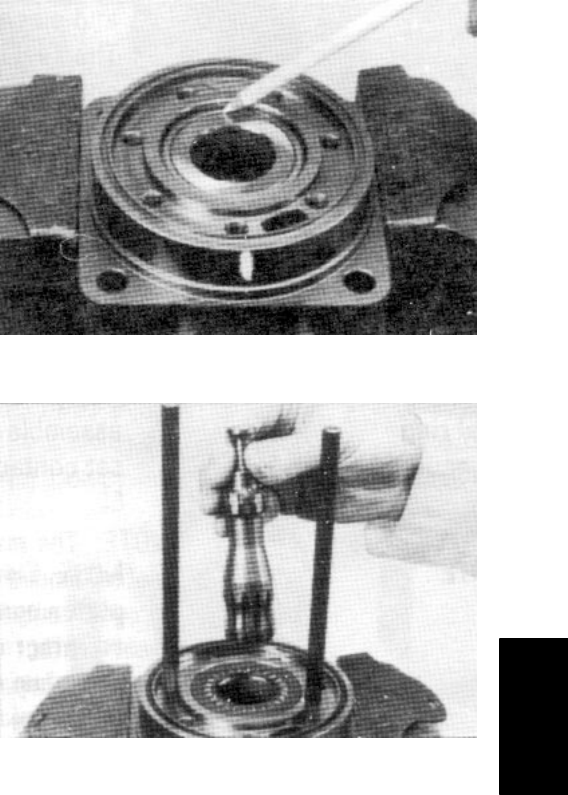
9. Apply a small amount of clean grease to a new seal
ring (5) and insert it into the housing (3) seal ring groove.
Note: One or two alignment studs screwed finger tight
into housing (18) bolt holes, approximately 180 degrees
apart, will facilitate the assembly and alignment of com-
ponents as required in the following procedures. The
studs can be made by cutting off the heads of 3/8–24
UNF 2A bolts so they are 0.5 inch (12.7 mm) or longer
than cap screw (14).
Note: Use any alignment marks put on the coupling
shaft (11) and drive link (13) before disassembly to as-
semble the drive link splines in their original position in
the mating coupling shaft splines.
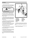
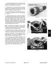
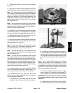
10. Install drive link (13) with the long splined end down
into the coupling shaft (11). Engage the drive link splines
so they mesh with the coupling shaft splines (Fig. 47).
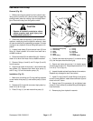
11. Assemble wear plate (18) over the drive link (13)
and alignment studs onto the housing (3).
12. Apply a small amount of clean grease to a new seal
ring (5) and assemble it into the seal ring groove on the
wear plate side of the stator (21).
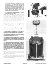
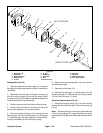
Note: The rotor set consists of the rotor (19), vanes
(20), and stator (21). Rotor set components may be-
come disassembled during service procedures.
Note: It may be necessary to turn one alignment stud
out of the housing (3) temporarily to assemble rotor set
over the drive link (13).
Note: The rotor set rotor counterbore side must be
down against wear plate for drive link clearance and to
maintain the original rotor–drive link spline contact. A ro-
tor set without a counterbore and that was not etched
before disassembly can be reinstalled using the drive
link spline pattern on the rotor splines if apparent, to de-
termine which side was down. The rotor set seal ring
groove faces toward the wear plate (18).
13. Install assembled rotor set onto wear plate (18) with
rotor (19) counterbore and seal ring side down. The
splines should mesh with the drive link (13) splines.
14. If disassembled rotor (19), stator (21), and vanes
(20) cannot be readily assembled by hand, assemble
with the following procedures:
A. Place stator (21) onto wear plate (18) with seal
ring (5) side down. Be sure the seal ring is in place.
Figure 46
Figure 47
B. If assembly alignment studs are not being uti-
lized, align stator (21) bolt holes with wear plate (18)
and housing (3) bolt holes. Screw two cap screws
(14) finger tight into bolt holes approximately180 de-
grees apart to retain stator and wear plate station-
ary.
Note: If the manifold (22) side of the rotor (19) was
etched during wheel motor disassembly, this side
should be up. If the rotor is not etched and does not have
a counterbore, use the drive link spline contact pattern
apparent on the rotor splines to determine the rotor side
that must be against the wear plate.
C. Place rotor (19) with counterbore down, if appli-
cable, into stator (21), and then onto wearplate (18)
so rotor splines mesh with drive link (13) splines.
IMPORTANT: Do not force rotor vanes into place,
the coating applied to stator vane pockets could
shear off.
D. Assemble six vanes (20), or as many vanes that
will readily assemble into the stator vane pockets.
Hydraulic
System