


Reelmaster 2300–D/2600–D Hydraulic SystemPage 4 – 47
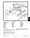
Note: Be ready to catch the shuttle valve or relief valve
components that will fall out of the end cover valve cavity
when the plugs are removed.
Note: O–ring (25) is not included in the seal kit, but
can be serviced separately if required.
Note: The insert and ,if included, the orifice plug in the
end cover assembly (24) must not be removed as they
are serviced as an integral part of the end cover.
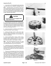
4. If the end cover (24) is equipped with shuttle valve
components (left–hand motor only), remove both pre-
viously loosened plugs and O–rings (25).
5. Remove commutator ring (23).
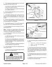
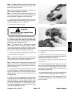
CAUTION
Use eye protection such as goggles when
using compressed air
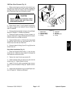
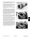
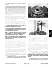
6. Remove commutator (16) and commutator seal
(15). Remove commutator seal from the commutator
using an air hose to blow air into the ring groove until the
commutator seal is lifted out (Fig. 34)
Note: The manifold (22) is constructed of plates
bonded together to form an integral component not sub-
ject to further disassembly for service. Compare config-
uration of both sides of the manifold to make sure that
same surface is reassembled against the rotor set.
7. Remove manifold (22). Remove seal rings (5) that
are on both sides of the manifold.
Note: The rotor set consists of the rotor (19), vanes
(20), and stator (21). Rotor set components may be-
come disassembled during service procedures.
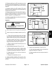
Note: Marking all rotor components and mating spline
components for exact repositioning at assembly will
make sure maximum wear life and performance of rotor
set and wheel motor.
8. Mark surface of rotor (19) and stator (21) that is fac-
ing up with etching ink or a grease pencil before remov-
ing from the wheel motor. This will make sure correct
reassembly of the rotor into the stator and the rotor set
into wheel motor.
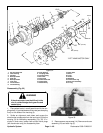
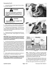
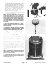
9. Remove rotor set and wearplate (18) together, and
retain the rotor set in its assembled form with the same
vane (20) to stator (21) contact surfaces. The drive link
(13) may come away from the coupling shaft (11) with
the rotor set and wearplate. You may have to shift the ro-
tor set on the wearplate to work the drive link out of the
rotor (19) and wearplate (Fig. 35).
Figure 34
Figure 35
10. Remove seal ring (5) that is between the rotor set
and wearplate.
11. Remove drive link (13) from the coupling shaft (11)
if it was not removed with rotor set and wear plate (18).
Remove seal ring (5) from housing (3).
12. Remove thrust bearing (12) from the top of the cou-
pling shaft (11).
13. Check exposed portion of coupling shaft (11) to be
sure you have removed all signs of rust and corrosion
which might prevent its withdrawal through the dirt and
water seal (1) and outer bearing (2). Crocus cloth or fine
emery paper may be used.
14. Remove coupling shaft (11); push on the output end
of the shaft. Remove seal ring (5) from housing (3).
15. Remove housing (3) from the vise and invert it. Re-
move dirt and water seal (1). A blind hole bearing or seal
puller is required.
Hydraulic
System