


Reelmaster 2300–D/2600–DPage 7 – 8Cutting Units
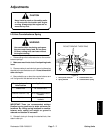
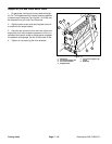
Height–of–Cut and Leveling Rear Roller
Note: Both floating and fixed cutting units can use this
method for making height of cut adjustments and level-
ing both front and back rollers.
1. Position cutting unit on a flat level table or board.
2. Slightly loosen (crack) nut securing each roller
bracket to the angle bracket.
3. For the rear roller, adjust support cap screw to
achieve 5/8” +
1/16 (15.9 mm "1.6) dimension between
both Height–of–Cut supports and rear
roller brackets.
4. For the front roller, adjust support cap screw to
achieve 1” +
1/16 (25.4 mm "1.6) dimension between
both Height–of–Cut supports and
front
roller brackets.
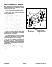
5. For the rear roller, remove hairpin cotters securing
rear
Height–of–Cut pins and reinstall in the 1/2” setting
as indicated on the rear Height–of–Cut plate.
6. For the front roller, remove hairpin cotters securing
front Height–of–Cut pins and reinstall in the 1/4” setting
as indicated on the front Height–of–Cut plate to allow
clearance between front roller and table.
7. Position a 1/2” or thicker bar under the reel blades
and against the front face of the bedknife. Make sure bar
covers the full length of reel blades.
8. Verify that rear roller is level, by attempting to insert
a piece of paper under each end of roller. The paper
should not fit between the roller and the table.
9. Level rear roller by adjusting the appropriate sup-
port cap screw on rear roller supports until the roller is
parallel and the entire length of roller contacts the table.
A piece of paper inserted between the roller and the
table should not fit.
10. When roller is level, adjust both rollers to desired
Height–of–Cut with pins. Tighten nuts securing roller
brackets and replace hairpin cotters to the Height of
cut pins.
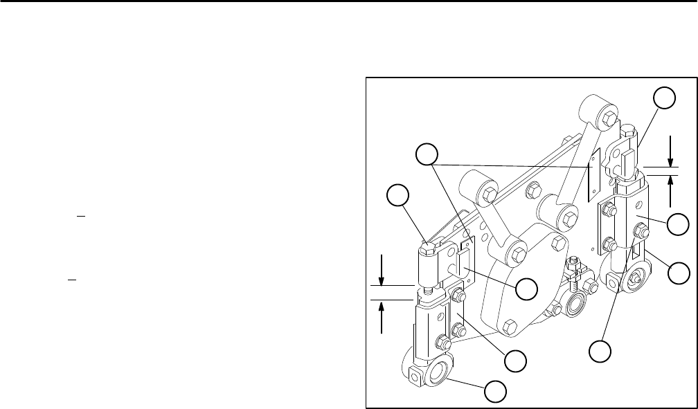
1. Nut
2. Rear roller bracket
3. Front roller bracket
4. Angle bracket
5. Support capscrew
6. Height–of–Cut support
7. Height–of–Cut pins
8. Height–of Cut plate
Figure 6
1”
5/8”
3
4
7
5
2
4
6
1
8