Reelmaster 2300–D/2600–D
Page 6 – 6
Wheels and Brakes
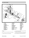
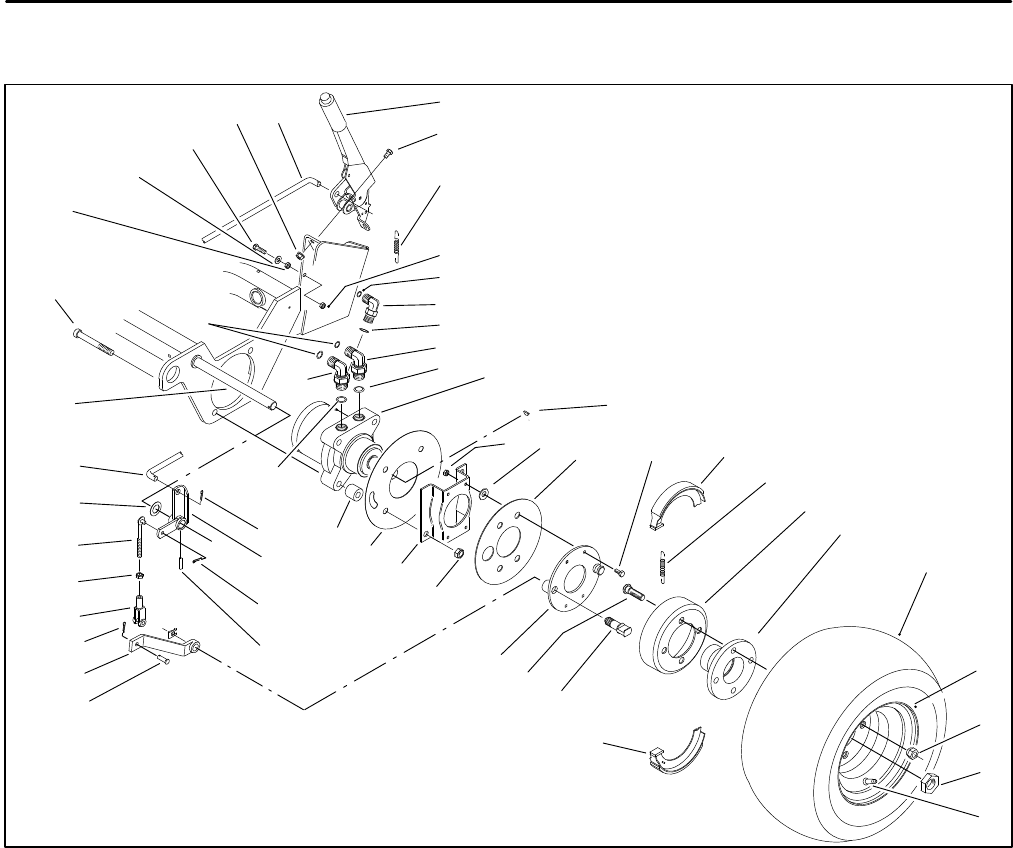
Front Wheel and Brake
17
3
6
5
9
2
15
11
7
4
10
2
8
24
11
16
30
14
27
28, 29
27
31
32
27
33
34
35
36
6
37
22
21
20
18
19
17
23
1
25
26
13
40
41
42
43
44
12, 38
39
45
46
47
47
48
49
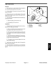
Figure 4
1. Lock nut
2. Lock nut
3. Flat washer
4. Hex head screw
5. Flange nut
6. Adjusting rod
7. Parking brake assembly
8. Flanged screw
9. Spring
10. Hydraulic fitting
11. Elbow fitting
12. Wheel motor (RH)
13. Lock nut
14. Flat washer
15. Grass brake shield
16. Hex head screw
17. Brake shoe
18. Wheel hub
19. Brake drum
20. Lug tire
21. Lock rim
22. Lug nut
23. Wheel hub stud
24. Socket head screw
25. Brake bracket
26. Wheel shield
27. Cotter pin
28. Brake arm assembly (RH)
29. Brake arm assembly (LH)
30. Roll pin
31. Clevis pin
32. Brake lever assembly
33. Clevis
34. Hex nut
35. Adjusting rod
36. thrust washer
37. Brake shaft
38. Wheel motor (LH)
39. Spacer
40. Lock nut
41. Valve stem
42. Extension spring
43. Pivot pin
44. Brake plate
45. O–ring
46. O–ring
47. O–ring
48. O–ring
49. Key
LEFT WHEEL SHOWN
Removal
1. Park machine on a level surface. Ensure engine is
off.
2. Make sure brake is in the OFF position.
3. Lift front wheel off the ground using a jack. Block
front and rear of other wheels.
4. Remove lug nuts (22) and tire and rim assembly (20
and 21). Remove lock nut (40) from wheel hub (18).


