


Reelmaster 2300–D/2600–D Hydraulic SystemPage 4 – 29
Procedure for Manifold Relief Valve Pressure
Check:
1. Make sure hydraulic oil is at normal operating tem-
perature by operating the machine for approximately 10
minutes.
2. Make sure machine is parked on a level surface with
the cutting units lowered. Make sure engine is off and
the parking brake is engaged.
3. Make sure the hydraulic tank is full.
CAUTION
Operate all hydraulic controls to relieve
system pressure and avoid injury from
pressurized hydraulic oil.
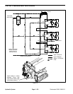
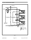
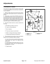
4. Clean hose connection and right hand reel motor.
Disconnect the hose leading from the right hand reel
motor to port M2 on the hydraulic manifold.
IMPORTANT: Make sure oil flow indicator arrow on
the flow gauge is showing that the oil will flow from
the hose through the tester and into the motor.
5. Install tester in series with the hose and motor. Make
sure the flow control valve is fully open.
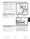
6. Make sure backlap knob on the valve block is in the
mow position. Make sure reel speed knob is set to posi-
tion 9 or greater.
CAUTION
Keep away from reels during test to pre-
vent personal injury from the rotating reel
blades.
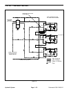
7. Start engine and move throttle to full speed (3200 "
100 RPM). Engage the cutting units.
8. Watch pressure gauge carefully while slowly clos-
ing the flow control valve until the manifold relief opens.
9. System pressure should be from 2700 to 3300 PSI.
A. If specification is not met, adjust relief valve.
B. If this specification is met, go to step 11.
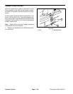
10. Adjusting the relief valve pressure as follows:
A. Remove the cap from the relief valve.
B. To increase the relief valve pressure set point,
use an allen wrench and turn set screw slightly
clockwise.
C. To decrease the relief valve pressure set point,
use an allen wrench and turn set screw slightly
counterclockwise.
D. Repeat steps 1 through 10 above until the relief
valve pressure set point is correct. Reinstall cap on
valve when valve is set properly.
E. If the relief valve pressure set point can not be
adjusted to specification, go to step 11 and replace
the relief valve.
11. Disengage cutting units. Shut off engine.
12. Disconnect tester from manifold and hose. Recon-
nect hose to the pump.
Hydraulic
System