


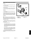

Reelmaster 2300–D/2600–D Page 7 – 13 Cutting Units
Hydraulic Motor Removal and Installation
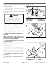
Removal
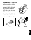
1. Remove two capscrews holding the hydraulic motor
to the bearing housing.
2. Remove hydraulic motor and spider coupling from
the bearing housing.
3. Position the hydraulic motor away from the cutting
unit prior to removing or working on the cutting unit.
Inspection
1. Inspect spider coupling for wear. Replace worn cou-
pling with new one.
2. Check coupling inside bearing housing. If coupling
is loose remove and check for worn threads. Replace
coupling if threads are worn. Reinstall coupling (see
Reel Removal and Bearing Replacement, Install Reel).
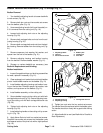
Installation
Note: The cutting unit can be installed with the hy-
draulic motor driving the unit from the other side. If so,
remove the bearing housing cap screws, cover, and
cover gasket; reinstall them on the opposite bearing
housing from the motor.
1. Dip spider coupling in No. 2 General Purpose Lithi-
um Base Grease. Reinstall spider coupling into the
bearing housing.
2. Reinstall hydraulic motor.
A. On models without the O–ring, clean bearing
housing face and place a bead of RTV around the
face of the housing to form a seal. Mount hydraulic
motor to the bearing housing. Secure motor with the
two capscrews.
B. On models with O–rings, replace if necessary.
Make sure O–ring is on the front plate of the motor.
Mount hydraulic motor to the bearing housing. Se-
cure motor with the two capscrews.
3. Grease bearing housing sufficiently to fill housing
with grease (see Greasing Bearings, Bushings, and Piv-
ot Points).
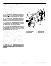
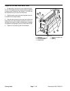
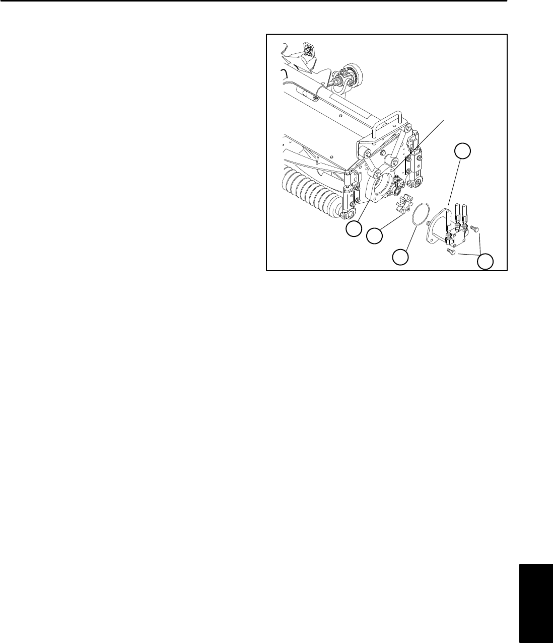
Figure 14
1. Capscrew
2. Hydraulic motor
3. Bearing housing
4. Spider couping
5. O–ring
4
2
1
3
5
HOUSING
FACE
Cutting Units