


Reelmaster 3100−D Hydraulic System (Rev. C)
Page 4 − 33
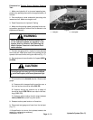
Procedure for Piston Pump (P3) Flow and Traction
Relief Pressure Test:
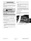
1. Make sure hydraulic oil is at normal operating tem-
perature by operating the machine for approximately 10
minutes.
2. Park machine on a level surface with the cutting units
lowered and off. Make sure engine is off.
3. Read Precautions for Hydraulic Testing.
4. Make sure that traction pedal is adjusted to the neu-
tral position (see Adjust Traction Drive for Neutral in the
Adjustments Section).
WARNING
One front wheel and the rear wheel will be off the
ground during testing. Make sure machine is sup-
ported so it will not move and accidentally fall to
prevent injuring anyone under machine.
5. Block up one front traction wheel and the rear wheel
off the floor to allow flow through the traction circuit; dis-
connect brake linkage to this wheel (see Wheels and
Brakes − Chapter 7).
6. Chock remaining front wheel to prevent movement
of the machine. Apply parking brake.
7. Attach a heavy chain to the rear of the machine frame
and something immovable in the shop.
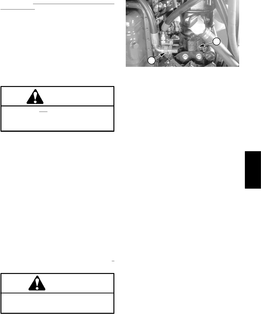
8. Disconnect hose from the lower hydraulic fitting on
the bottom of the hydrostat.
NOTE: An alternate testing location would be at the hy-
draulic hose connection to the hydraulic tube under the
left floor plate.
9. Install tester in series with the pump and the discon-
nected hose. Make sure the flow control valve is fully
open.
10.Start engine and move throttle to full speed (2650 +
50 RPM).
CAUTION
Use extreme caution when taking gauge read-
ings. The front tire on the ground will be trying to
move the machine forward.
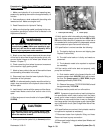
11.Slowly push traction pedal fully to forward position.
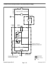
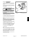
1. Lower hydraulic fitting 2. Piston pump
Figure 18
1
2
12.Verify traction relief valve setting by closing flow con-
trol valve. System pressure should be from 3000 to 3125
PSI as the relief valve lifts. If pressure can not be met or
is exceeded with traction pedal fully depressed, release
traction pedal and open flow control valve fully.
13.If specification is not met consider the following:
A. The traction belt may be worn and slipping (see
Replace Traction Belt).
B. The relief valve leaks or is faulty and needs re-
placement.
C. The hydrostat needs to be repaired or replaced
as necessary.
14.If the traction relief valve tests out properly, verify
pump flow as follows:
A. Push traction pedal in the forward direction until
pressure gauge reads 1000 PSI. Verify with a photo-
tac that the pump speed is 2350 RPM (engine
speed approximately 2000 RPM).
B. Observe flow gauge. TESTER READING should
be approximately 12.5 GPM.
15.Release traction pedal and turn off machine.
NOTE: If pressure is good under no load, but drops be-
low specification when under traction load, the piston
pump and/or wheel motor(s) should be suspected of
wear. When a pump and/or motor is worn or damaged,
the charge pump is not able to keep up with internal leak-
age in the traction circuit (See Charge Relief Valve Pres-
sure Test).
16.If specifications are not met, the hydrostat needs to
be repaired or replaced as necessary.
17.Disconnect tester from hydraulic fitting and hose.
Reconnect hose to pump connection.
18.Reconnect brake linkage to wheel (see Wheels and
Brakes − Chapter 7).
Hydraulic
System