


Reelmaster 3100−D Hydraulic System (Rev. C)
Page 4 − 19
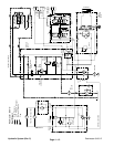
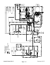
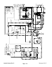
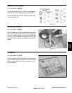
Sidewinder Circuit
The gear pump (P2) is directly coupled to the hydrostat
through gear pump (P1). It supplies hydraulic pressure
(charge pressure) for raising and lowering the cutting
units, operating the sidewinder unit, and maintaining
100 to 150 PSI (6.9 to 10.0 bar) to the low pressure side
of the traction circuit. The pump takes its suction from
the hydraulic reservoir.
During conditions of not lifting or lowering the cutting
units, flow from the gear pump is by−passed through the
power steering valve, 2−spool valve, and hydraulic
manifold directly to the hydrostat and the charge relief
valve. Flow then returns to the hydraulic tank.
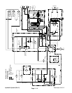
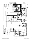
Shift Sidewinder Right
When the sidewinder is to be shifted right, the 2−spool
valve is positioned by moving the cutting unit shift lever
to RIGHT. Flow is directed to the cap end of the side-
winder cylinder. Hydraulic pressure against the cylinder
piston moves the rod causing the sidewinder cylinder to
extend right. At the same time, the piston pushes the hy-
draulic fluid out of the cylinder, back through the spool
and hydraulic manifold, and to the hydrostat. When the
cutting unit shift lever is released, spring action returns
the valve to its original position and by−passes flow back
to the hydrostat and stopping cylinder movement. The
cylinder position is locked in place since there is no com-
plete circuit of flow to and from the lift cylinders.
Shift Sidewinder Left
When the sidewinder is to be shifted left, the 2−spool
valve is positioned by moving the cutting unit shift lever
to LEFT. Flow is directed to the rod end of the sidewinder
cylinder. Hydraulic pressure against the cylinder piston
moves the rod causing the sidewinder to retract left. At
the same time, the piston pushes the hydraulic fluid out
of the cylinder, back through the spool and hydraulic
manifold, and to the hydrostat. When the cutting unit
shift lever is released, spring action returns the valve to
its original position and by−passes flow back to the hy-
drostat stopping cylinder movement. The cylinder posi-
tion is locked in place since there is no complete circuit
of flow to and from the lift cylinders.
Hydraulic
System