


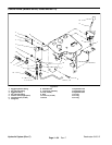

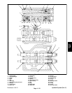


Reelmaster 3100−DHydraulic System (Rev. C)
Page 4 − 88
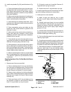
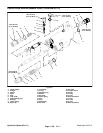
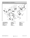
Disassembly
1. Plug all ports and clean the outside of the valve thor-
oughly.
2. Remove spool cap and slide the spool assembly
from its bore.
3. Remove O−ring and bushing from the spool assem-
bly.
4. Remove O−ring from the spool bore end that is oppo-
site the spool cap.
NOTE: Disassemble spool assembly only if the retain-
ing ring, spacer, spring, or washer need replacing.
5. Remove seat retaining plug, back−up washer, O−
ring, and check spring from the valve body.
6. Remove check poppet, seat, O−ring, and plunger
from the valve body.
7. Remove solid plug, back−up washer, and O−ring
from the opposite end of the plunger.
8. Remove plug and O−ring from the top of the valve
body next to the detent plug.
9. Remove detent plug and O−ring from the valve body.
Remove disc spring, and detent plunger from the body.
Inspection
1. Inspect spool and spool bore for wear. If wear is ex-
cessive, replace valve with new one.
2. Inspect springs and replace as necessary.
3. Inspect plunger, detent plunger, and check poppet
for wear. Replace as necessary.
4. Inspect seat, spacer, and bushing for wear. Replace
as necessary.
5. Inspect disc and washer. Replace as necessary.
6. Inspect cap and plugs for damaged threads and O−
ring sealing surfaces. Replace as necessary.
Assembly
IMPORTANT: Do not wipe parts with paper towels or
rags. Lint free cloth must be used to prevent lint
from causing damage to the hydraulic system.
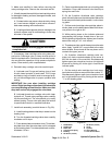
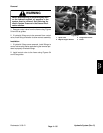
CAUTION
Use eye protection such as goggles when using
compressed air.
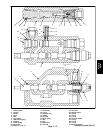
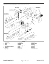
1. Clean all metal parts with solvent and blow dry with
compressed air.
2. Replace check poppet, O−rings, and back−up wash-
ers with new ones.
3. Install new O−rings into the valve body.
4. Slide bushing and new O−ring over the spool.
5. If the spool was disassembled, install washer, spool
spring, spacer, and retaining ring to the spool.
6. Lubricate spool liberally with clean hydraulic fluid
and install into its proper bore.
7. Install spool cap into valve body. Torque cap from 20
to 25 ft−lb (27 to 34 N−m).
8. Install O−ring, back−up washer, and solid plug into
the bore on the opposite end of the plunger. Torque plug
from 30 to 35 ft−lb (41 to 48 N−m).
9. Lubricate plunger liberally with clean hydraulic fluid
and install into its valve body bore.
10.Install new O−ring, seat, check poppet, and check
spring into the plunger bore.
11.Install O−ring, back−up washer, and seat retaining
plug into the plunger bore. Torque plug from 30 to 35 ft−
lb (41 to 48 N−m).
12.Install O−ring and plug into the top of the valve body
next to the detent plug bore. Torque plug from 10 to 12
ft−lb (14 to 16 N−m).
13.Lubricate plunger detent, spring, and disc liberally
with clean hydraulic fluid and install into its valve body
bore.
14.Install O−ring and detent plug into its proper bore.
Torque plug from 30 to 42 ft−lb (41 to 57 N−m).