


Reelmaster 3100−DPage 5 − 36Electrical Systems (Rev. C)
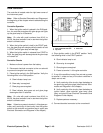
Indicator Lights (Serial Numbers Above 240000000)
Charge Indicator Light
The charge indicator light should come on when the igni-
tion switch is in the ON position with the engine not run-
ning. Also, it should illuminate with an improperly
operating charging circuit while the engine is running.
Engine Oil Pressure Light
The engine oil pressure light should come on when the
ignition switch is in the ON position with the engine not
running. Also, it should illuminate with the engine run-
ning if the engine oil pressure drops to an unsafe level.
IMPORTANT: If the oil pressure indicator light is il-
luminated with the engine running, shut off the en-
gine immediately.
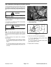
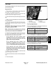
To test the oil pressure light and circuit wiring, ground the
wire attached to oil pressure switch located on the en-
gine near the oil filter. Turn ignition switch to the ON posi-
tion; the engine oil pressure light should come on
indicating correct operation of the indicator light and cir-
cuit wiring.
High Temperature Warning Light
If the engine coolant temperature reaches 221
o
F
(105
o
C) (approximate), the high temperature warning
light should come on.
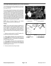
To test the high temperature warning light and circuit wir-
ing, turn ignition switch to the ON position and ground
the wire attached to high temperature sender located on
the engine water pump housing (see Temperature
Sender in this Chapter). The high temperature warning
light should illuminate.
Glow Plug Indicator Light
The glow plug light should come on when the ignition
switch is placed in the ON position prior to placing the
ignition switch in START. The light should stay lit for
approximately 6 seconds while the ignition switch is left
in the ON position.
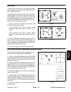
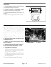
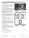
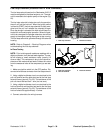
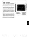
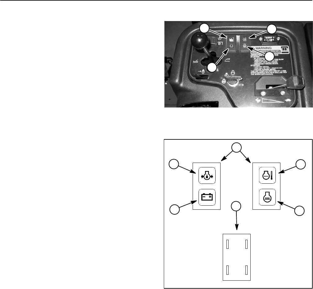
Testing Indicator Lights
1. Apply 12 VDC to terminals 1A and 2A (Fig. 18).
2. Ground terminals 1B and 2B (Fig. 18).
3. Both indicator lights should illuminate.
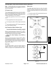
1. Charge indicator
2. Engine oil pressure
3. High temp shutdown
4. Glow plug indicator
Figure 17
3
4
1
2
Figure 18
1. Charge indicator
2. Engine oil pressure
3. High temperature
4. Glow plug indicator
5. Indicator light front
6. Indicator light back
1A (+)
2A (+)2B (−)
1B (−)
4
3
5
2
1
6