


Rev. CReelmaster 3100−D Page 6 − 7 Wheels, Brakes,and Miscellaneous
IMPORTANT: Do not hit wheel hub, wheel hub puller
or wheel motor with a hammer during removal or
installation. Hammering may cause damage to the
hydraulic wheel motor.
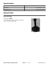
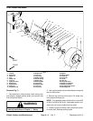
5. Using hub puller (see Special Tools), loosen wheel
hub from wheel motor.
6. Remove lock nut, hub, and brake drum from motor
shaft. Locate and retrieve woodruff key.
7. Remove cotter pin from the adjustment rod. Sepa-
rate adjustment rod from the brake lever.
NOTE: The brake lever, backing plate, retaining clip,
return springs, brake shoes, and cam shaft can be re-
moved as a complete brake assembly.
8. If it is desired to remove the brake assembly from
the brake bracket, remove four cap screws and lock nuts
securing the assembly to the bracket.
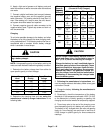
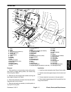
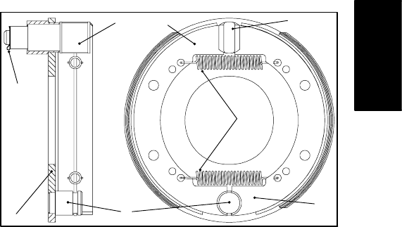
9. Disassemble brake assembly as follows (Fig. 8):
A. Remove return springs from the brake shoes. Re-
move brake shoes from the backing plate.
B. Matchmark brake cam and brake lever to assure
proper alignment during reassembly. Remove re-
taining clip from the brake cam. Pull brake lever from
the cam. Remove cam from backing plate.
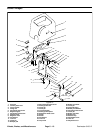
10.The brake bracket and wheel shield can be removed
as follows:
A. Remove lock nuts, spacers, and cap screws se-
curing the brake bracket, wheel shield, and hydraulic
motor to the frame.
B. Separate bracket and shield from the frame.
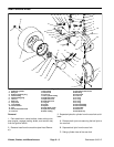
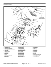
Installation (Fig. 7)
1. Insert four cap screws through the frame, hydraulic
motor, spacers, wheel shield, and brake bracket. Se-
cure with lock nuts, but do not fully tighten.
2. Assemble brake assembly as follows (Fig. 8):
A. Secure backing plate to the brake bracket with
four cap screws and lock washers.
B. Apply antiseize lubricant to cam shaft splines. In-
sert cam shaft through the backing plate.
C. Attach brake lever to the cam shaft. Make sure
matchmarks are aligned properly. Secure lever to
shaft with retaining clip.
D. Lubricate brake shoe pivot points with a light
coating of grease.
E. Position both brake shoes on the backing plate so
that the concave heels attach to the anchor pin.
F. Insert both return springs into the holes of both
brake shoes. Make sure shoes fit snuggly against
the anchor pin and cam.
3. If the brake lever, backing plate, retaining clip, return
springs, brake shoes, and cam shaft were removed as
a complete brake assembly, secure backing plate to the
brake bracket with four cap screws and lock washers.
Tighten fasteners.
4. Attach adjustment rod to the brake lever. Secure ad-
justment rod with cotter pin.
5. Thoroughly clean wheel motor shaft and wheel hub
taper.
6. Install woodruff key to the slot on the hydraulic motor
shaft. Slide wheel hub and brake drum assembly onto
the shaft.
7. Secure wheel hub and brake drum to the hydraulic
motor shaft with lock nut.
NOTE: For proper brake operation, the brake shoes
and backing plate must be concentrically aligned with
the brake drum.
8. To align brake shoes and drum, apply parking brake.
Then tighten four socket head screws and lock nuts that
secure the brake bracket and wheel motor to the frame.
9. Place wheel onto drive studs and wheel hub. Secure
wheel with lug nuts on drive studs.
10.Lower wheel to ground. Torque lug nuts from 45 to 65
ft−lb (61 to 88 N−m) in a criss−cross pattern. Torque lock
nut from 250 to 400 ft−lb (339 to 542 kg−m).
11.Check and adjust brakes (see Adjust Brake).
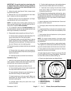
1. Return spring
2. Brake shoe (toe end)
3. Brake shoe (heel end)
4. Backing plate
5. Retaining clip
6. Cam shaft
7. Anchor pin
Figure 8
1
4
6
7
3
2
5
6
Wheels, Brakes,
and Miscellaneous