


Reelmaster 3100−D Page 7 − 17 Cutting Units
Reel Removal and Bearing Replacement
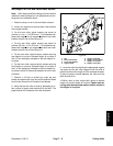
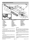
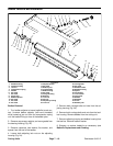
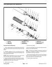
Remove Reel (Fig. 22)
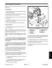
1. Remove hydraulic motor from the cutting unit (see
Hydraulic Motor Removal and Installation). Remove
cutting unit from the machine (see Cutting Unit Removal
and Installation).
2. Remove bedbar assembly from the cutting unit (see
Bedbar Removal and Installation).
3. Remove front roller from the cutting unit (see Roller
Removal and Installation).
Note: A 3/8−inch drive ratchet with an extension will
fit into the square hole of the coupling.
4. Unscrew reel coupler (LH) from the reel. This cou-
pler is left hand threaded. Unscrew reel coupling (RH)
from the reel. This coupler is right hand threaded.
IMPORTANT: Support reel to prevent it from dropping
when the bearing housings are removed.
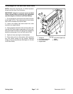
5. Remove cap screws from both bearing housings.
Pull bearing housings and bearings from reel. Remove
reel from the cutting unit.
6. Rotate bearings within the bearing housings, and re-
move bearings from both bearing housings through the
loading grooves.
Inspect Reel (Fig. 22)
1. Replace reel if the diameter has decreased to the
service limit (see Reel Grinding Specification in Prepar-
ing Reel For Grinding).
2. Replace reel if blades are bent or cracked.
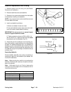
3. Check for a bent reel shaft by placing the reel shaft
ends in V−blocks. Replace reel if the reel shaft is bent.
Install Reel (Fig. 22)
1. Inspect bearings and replace if worn or damaged.
Replace both bearings as a set.
2. Make sure bearing seating surfaces and threads on
reel shaft ends are clean. Apply anti−seize lubricant to
both bearing seating surfaces.
3. Align reel inside the cutting unit with the bearing
housing holes. The reel must be positioned so that the
grooved end of the shaft (left−hand threads) is on the left
side of the cutting unit.
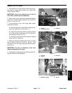
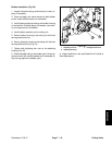
4. Clean inside of the bearing housing before installing.
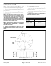
Install bearing into bearing housing as follows:
A. Load bearing through loading grooves.
B. Position bearing so its outer grease holes will be
90
o
to the loading grooves.
C. Rotate bearing inside of the housing so the ex-
tended part of the inner race is facing the inside of the
housing.
5. Slide bearings and bearing housings onto the reel
shaft.
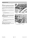
6. Make sure bearing housings are installed with the
grease fittings pointing up and to the front of the cutting
unit.
7. Secure bearing housings and bearings on the reel
shaft ends and cutting unit with the cap screws.
8. Remove grease from the threaded end of reel cou-
plers and the reel shaft. Make sure grease is completely
removed.
9. Apply removable Loctite 242 or equivalent to reel
coupler threads. Do not get Loctite on the bearing
seal.
10.Screw reel coupler (RH) to the reel. This coupling
is right hand threaded. Screw reel coupler (LH) to the
reel. This coupling is left hand threaded. Torque both
couplers from 55 to 65 Ft−lb (74.6 to 88.1 N−m).
11.Install front roller to cutting unit (see Roller Removal
and Installation).
12.Install bedbar assembly to cutting unit (see Bedbar
Removal and Installation).
13.Install cover gasket, weights, and cap screws to the
bearing housing.
14.Complete cutting unit set−up and adjustment se-
quence (see Adjustments section).
15.Grease both bearings (see Greasing Bearings,
Bushings, and Pivot Points).
Cutting Units