


Reelmaster 3100−DPage 7 − 30Cutting Units
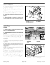
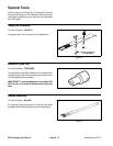
Skid Kit Installation
1. Remove front roller from the cutting unit (see Roller
Removal and Installation).
2. Align skid slots with the angle bracket holes on the
cutting unit.
3. Secure skid to the cutting unit with both flange head
screws, flat washers, and lock nuts.
4. Repeat steps 1 through 3 on the other side of the cut-
ting unit.
5. Adjust skid height as necessary by loosening lock
nuts and flange head screws, then retighten fasteners.
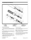
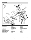
1. Skid
2. Angle bracket holes
3. Flange head screw
4. Flat washer
5. Lock nut
3
1
4
5
2
Figure 37
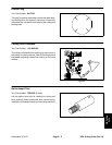
Carrier Frame
Removal
1. Make sure cutting unit and carrier frame are placed
firmly on a flat working surface.
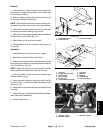
2. Remove tipper chain from the top of the carrier frame
(Fig. 38).
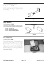
3. Remove lock nut, both flat washers, and large cap
screw securing mounting links to the carrier frame. Re-
move carrier frame from the cutting unit (Fig. 39).
Installation
1. Make sure cutting unit is placed firmly on a flat work-
ing surface.
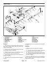
2. Position carrier frame (flat edge forward) onto the
cutting while aligning mounting holes with all mounting
links (Fig. 39).
NOTE: A flat washer must be on each side of all mount-
ing links during installation.
3. Secure all four mounting links to the carrier frame
with both flat washers, large cap screw, and lock nut.
Torque lock nut and cap screw to 31 Ft−lb (42 N−m).
4. Route tipper chain up through the slot in each end of
the carrier frame. Secure chain to the top of the carrier
frame with washer, cap screw, and lock nut (Fig. 38).
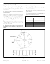
1. Tipper chain
2. Carrier frame
3. Washer
4. Cap screw
5. Lock nut
Figure 38
1
2
4
3
5
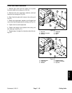
1. Carrier frame 2. Mounting link
Figure 39
FRONT
1
2