


Reelmaster 3100−D Page 7 − 15 Cutting Units
Cutting Unit Removal and Installation
Removal
1. Position machine on a clean, level surface. Lower
cutting units, stop engine, engage parking brake, and
remove key from the ignition switch.
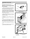
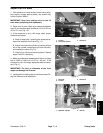
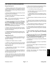
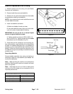
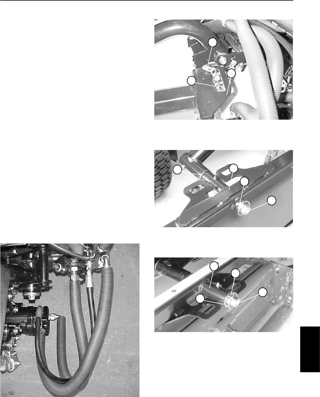
2. On the front cutting units, detach chain from the cut-
ting unit carrier frame by removing the lock nut and cap
screw (Fig. 19).
3. Remove hydraulic motor from the cutting unit (see
Reel Motor Removal).
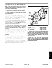
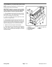
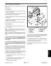
4. Remove lynch pin from pivot shaft (Fig. 20 and 21).
5. Slide cutting unit carrier frame and thrust washer
from the pivot shaft.
Installation
1. On the front cutting units, slide thrust washer and
then cutting unit carrier frame onto pivot shaft (Fig. 20).
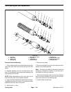
2. On the rear cutting unit, slide cutting unit carrier
frame and then thrust washer onto pivot shaft (Fig. 21).
3. Install lynch pin onto the pivot shaft (Fig. 20 and 21).
4. Install hydraulic motor to the cutting unit (see Reel
Motor Installation).
5. On front cutting units, attach chain to the cutting unit
carrier frame with cap screw and lock nut (Fig. 19).
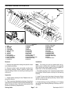
Figure 18
1. Chain
2. Cap screw & lock nut
3. Front carrier frame (RH
)
Figure 19
1
2
3
1. Lynch pin
2. Thrust washer
3. Pivot shaft
4. Front unit carrier frame
Figure 20
2
3
1
4
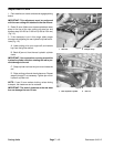
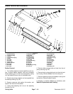
1. Lynch pin
2. Thrust washer
3. Pivot shaft
4. Rear unit carrier frame
Figure 21
2
3
1
4
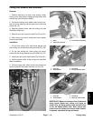
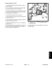
IMPORTANT: Make sure hoses are free of twists and
sharp bends. Route rear cutting unit hoses as
shown (Fig. 18). Raise cutting units and shift them
to the left (Model 03201 only). Rear cutting unit
hoses must not contact the traction cable bracket.
If required, reposition fittings and hoses.
Cutting Units